
Instruction Manual
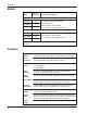

Specifications
Electrical
Input Signal
Frequency
Range
t 0-20 kHz (standard) (field-adjustable)
t 0-0.1 Hz (special order)
t 0-80 Hz (special order)
t 0-50K Hz (special order)
Waveforms t Accepts pulsed, sinusoidal, square, TTL, or CMOS
Input Signal
Sensitivity
t 25 mVrms (typical factory setting)
t 5 mVrms to 100 mVrms (field-adjustable)
t 50 Vrms (maximum for standard units)
t 1.0 volt threshold (requires input signal desensitizing)
Input
Impedance
t Nearly infinite at low signal levels
t 10 kΩ (min.) at signals exceeding +15.0 V peak, –1.0 V peak
Power Input t 115 Vac ±10%, 47-420 Hz
t 22–30 Vdc, maximum 5 W or 150 mAdc
t 220 Vac, 50/60 Hz (optional)
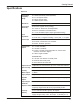
Proportional
Output
t 0–1 mAdc (standard)
t 4–20 mAdc (standard)
t 0–5 Vdc or 0–10Vdc (field-selectable; for external load
resistance of 20 kΩ or higher)
t Custom ranges available
MAXIMUM LOAD
t 1 kΩ with 115/ 220 Vac or 30 Vdc power
t 750 ohms with 22 Vdc power
t linear between 22 and 30 Vdc
Output Current Independent of load resistance up to the rated load resistance
Span/zero adj. ±5% (minimum) of fuIl-scale
Auxiliary
Meter Output
Proportional 0–1 mAdc, filtered, for meter or recorder loads up
to 750 Ω.
Supply Output Regulated +14 Vdc ±5%; 40 mAdc (maximum load)
Repeater
Output
Square wave 14 V peak-to-peak, zero based, positive going
Output Ripple
and Noise
0.1% of full-scale maximum over 10% to 100% of full-scale.
Response Time 150 milliseconds, 10% to 90% rise (standard). Full-scale
frequency ranges below 80 Hz are proportionally slower.
Linearity 0.1% of full-scale (0.05%, typical), all outputs.
Stability Less than 0.05% of full-scale change with a 10% change in
supply voltage. Temp. coeff. ±0.01% per °F (±0.018% per °C)
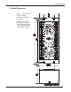
5
Getting Started