
Instruction Manual


Calibrating the SST-2000A/H
You must calibrate the SST-2000A/H if you have made a change in the full-scale
frequency range (changed contacts to DIP switch A).
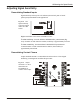
1 Disconnect any meter connected to terminals 7 & 8. Mark or
position the wires so they can be correctly reattached later.
2 Connect a digital voltmeter across terminals 7(–) & 8 (+).
3 Connect a frequency generator (e.g. F-16) at terminals 5 (HI) & 6
(COM). Use the frequency generator to input the new full-scale
frequency.
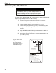
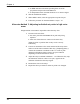
4 Adjust the FREQ RANGE TRIM potentiometer for 10.00 Vdc on
the voltmeter. (See Fig. 4-9.)
5 Reattach the meter that is normally connected to terminals 7(–) &
8 (+). Observe polarity.
22
Chapter 4
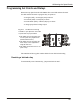
Calibrate the speed switch:
• immediately after any contact change in Switch A
• before adjusting set points or proportional output
WARNING
S.P.
2
S.P.
1
FREQ.
RANGETRIM
METERCAL
FREQUENCY
RANGESWITCH
SIGNAL
SENSITIVITY
AFTERSETTINGRANGE
SWITCH“A”,TRIMFOR10.0V
ATOPENTERMINALS8&7AT
FULLSCALEFREQUENCY.
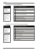
MAX
1,8:.08-.1
4,8:.17-.22
7,8:.38-.5
1,4,7,8:.63-.83
1,2,3,5,6,8:.83-1.09
1:.86-1.12
4:1.9-2.5
7:4.2-5.5
1,2,3,5,6:9.1-12
2,3,4,6,7:12-15.5
1,2,3,4,5,6,7:15.1-20
;2:1.1-1.4
;5:2.5-3.2
;7,2:5.3-6.9
;3:1.4-1.9
;6:3.2-4.2
;1,4,7:6.9-9.1
;2,8:.1-.13
;5,8:.22-.3
;7,2,8:.48-.63
;3,8:.13-.17
;6,8:.3-.38
8
7
6
5
4
3
2
1
O
F
F
A
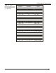
Fig. 4-9 The contact
arrangements for the
full-scale frequency
range switch (A) are on
underside of the top
plate.