SST-2000 Series Universal Speed Switch & Speed Transmitter An Operator’s Guide
Copyright Specifications and information herein are subject to change without notice. Dynalco Controls reserves the right to make changes to the equipment described herein to improve function or design. Although the information contained in this manual has been carefully reviewed and is believed to be reliable, Dynalco Controls does not assume any liability for special, indirect, incidental, or consequential damages arising out of the application or use of the equipment described herein.
Contents Chapter 1 Getting Started 1 About your speed switch . . . . . . . . . . . . . . . . . . . . . . . . . . . . . . . . . . . . . . . . 2 Models. . . . . . . . . . . . . . . . . . . . . . . . . . . . . . . . . . . . . . . . . . . . . . . . . . . . . . 4 Features . . . . . . . . . . . . . . . . . . . . . . . . . . . . . . . . . . . . . . . . . . . . . . . . . . . . . 4 Specifications . . . . . . . . . . . . . . . . . . . . . . . . . . . . . . . . . . . . . . . . . . . . . . . . .
Chapter 1 Getting Started
Chapter 1 About your speed switch WARNING When the SST-2000A/H Series Speed Switch/Transmitter is used as the primary overspeed shutdown device, it must be tested regularly.
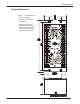
Getting Started Physical Dimensions Fig. 1-1 Top and side view of the SST-2000A/H. Dimensions in inches and (centimeters). Special explosion proof housings kits (complete with mounting hardware) are also available. See XP rated housings on page 6.
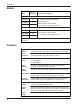
Chapter 1 Models Model No. Of Set Points 3rd Party Certification(s) A series – standard relays SST-2000A 0 SST-2200A 2 SST-2400A 4 CSA: general certification LR 92270 ABS: type approval CE: 89/336/EEC, Light Industrial CE: 72/23/EEC, Low Voltage Directive H series – hermetically sealed relays SST-2000H 0 SST-2200H 2 SST-2400H 4 CSA: Class I, Div. 2, Grp.
Getting Started Specifications Electrical Input Signal Frequency Range t 0-20 kHz (standard) (field-adjustable) t 0-0.1 Hz (special order) t 0-80 Hz (special order) t 0-50K Hz (special order) Waveforms t Accepts pulsed, sinusoidal, square, TTL, or CMOS Input Signal Sensitivity t 25 mVrms (typical factory setting) t 5 mVrms to 100 mVrms (field-adjustable) t 50 Vrms (maximum for standard units) t 1.
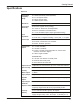
Chapter 1 Relays Logic Field-programmable by switches for: t overspeed/underspeed t energize/de-energize t latch/auto-reset t SPST/DPDT (2 DPDT set points maximum) A Series Contact Rating t 6.0 A @ 28 Vdc or 115 Vac (resistive) t 2.0 A @ 220 Vac t 1.0 A into 500 mH for up to 100,000 cycles t SPDT* *For DPDT, Relays 1 & 3 and 2 & 4 work together as separate DPDT trips. H Series Contact Rating t 5 A (resistive) @ 24 Vdc t 1.0 A @ 120 Vac t 0.
Getting Started Options Enclosures XP and NEMA rated enclosures are available. Open Pickup Relay 1 switches in the event of an open or disconnected magnetic pickup. Relay 1 will still react when its set point is traversed (field-configurable). NOTE: Not available with signal isolation transformer option.
Chapter 2 Installing the SST-2000A/H
Chapter 2 Mounting the unit The SST-2000A/H is installed using standard hand tools. It is generally mounted in a panel or enclosure using standard practices. About Electrical Connections Internal Commons, Isolation WARNING: AVOID DAMAGE WHEN DC-POWERED Install a current loop isolator between the 4–20mA output and the load if the load does not reference the same common as the SST-2000A/H.
Installing the SST-2000A/H Connecting Signal Inputs Connecting a PG-278 Pulser Connect signal source Common to terminal 6 on the SST-2000A/H. Connect signal HI to terminals on the SST-2000A/H. Fig. 2-2 Connecting a PG-278 Pulser to the SST-2000A/H. Terminals 11 and 30 on the SST-2000A/H are jumpered to create a one volt threshold.
Chapter 3 Powering External Devices
Chapter 3 Powering an SPD-100, SPD-700, or other frequency instruments The SST-2000A/H has a repeater output that can be used to power external frequency instruments. A square wave (14-volt peak-to-peak, zero-based, positive-going) is brought out at terminals 29 and 4 (common) to drive self-powered digital tachometers such as the SPD-100, SPD-700, and MTH-103D, or to use as a conditioned high level signal source into counters or other instruments.
Powering External Devices t Confirm the meter is properly connected to the SST-2000A/H. t Use a frequency generator (e.g. F-16) to apply full-scale frequency to terminal 5 (HI) & 6 (COM) on the SST-2000A/H. Maximum signal input is 50 Vrms for a standard unit. t Adjust the METER CALIBRATE potentiometer on the SST-2000A/H for the appropriate full-scale reading on each DPM-105. t Use a DPM-105 data sheet, if necessary, to calibrate the DPM-105 meters.
Chapter 3 Powering Zero Velocity Pickups and Other Loads The regulated 14 Vdc supply brought out at terminals 11 (+) & 4 (–) has a capacity of 40 mA. This output can power zero velocity pickups (e.g. M928) and digital indicators like a DPM-105. 1 Connect the M928 pickup as indicated in Fig. 3-5. 2 Jumper terminals 11 and 30 to desensitize the input signal to a 1.0 V threshold. 3 Adjust signal sensitivity if necessary. See page 27 for instructions on how to adjust input sensitivity. Fig.
Powering External Devices Driving an SPV-200 Solenoid Pneumatic Valve WARNING: TO AVOID SPV-200 COIL DAMAGE Use a current limiting resistor in series with the dc power source and the transferring relay contacts. The SPV -200 coil has a resistance of 50 Ω and requires 6 Vdc to trip. Switching the Regulated 14 Vdc Supply The regulated 14 Vdc supply at terminals 11 (+) & 4 (–) does not have the capacity to drive the SPV-200 continually.
Chapter 4 Calibrating the Speed Switch
Chapter 4 Locating the programming switch instructions Fig. 4-8 A full description of the programming switches and controls is located under the top plate of the SST-2000A/H. 1 Use a no. 1 or no. 2 Phillips screwdriver to remove the top plate of the switch.
Calibrating the Speed Switch Changing the full-scale input frequency range You can set the standard full-scale frequency range from as low as 0–80 Hz to as high as 0–20 kHz. 1 Remove the top plate from the SST-2000A/H to reveal the “A” DIP switches. 2 Use Table 4-1, page 23, or the underside of the top plate (bottom of Fig. 4-9, page 22) to determine the correct DIP switch settings. 3 Calibrate the SST-2000A/H using the procedure on page 22.
Chapter 4 Calibrating the SST-2000A/H WARNING Calibrate the speed switch: • immediately after any contact change in Switch A • before adjusting set points or proportional output You must calibrate the SST-2000A/H if you have made a change in the full-scale frequency range (changed contacts to DIP switch A). 1 Disconnect any meter connected to terminals 7 & 8. Mark or position the wires so they can be correctly reattached later. 2 Connect a digital voltmeter across terminals 7(–) & 8 (+).
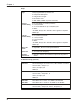
Calibrating the Speed Switch Table 4-1 Table of full-scale frequency and the corresponding switch “A” ON settings. Freq. Range (in kHz) Switch A ON Positions Freq. Range (in Hz) 0.08 - 0.10 1, 8 80 - 100 0.10 - 0.13 2, 8 100 - 130 0.13 - 0.17 3, 8 130 - 170 0.17 - 0.22 4, 8 170 - 220 0.22 – 0.30 5, 8 220 - 300 0.30 - 0.38 6, 8 300 - 380 0.38 – 0.50 7, 8 380 - 500 0.48 – 0.63 7, 2, 8 480 - 630 0.63 – 0.83 1, 4, 7, 8 630 - 830 0.83 – 1.09 1, 2, 3, 5, 6, 8 830 - 1,090 0.
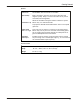
Chapter 4 Calibrating the 4-20 mA Proportional Output You must calibrate the speed switch if the standard proportional output of 4 to 20 mA is changed to : t 0–5 Vdc using switch C1, or t 0–10 Vdc using switch C2 To calibrate the new proportional output 1 Attach a digital voltmeter to terminals 9 (–) & 10 (+). 2 Apply 10% of the full-scale frequency to input terminals 5 (+), 6 (–). 3 Adjust the PROP OUT ZERO adjust potentiometer (See Fig.
Calibrating the Speed Switch Programming Set Points and Relays Remove the top plate from the SST-2000A/H to reveal DIP switches B and C. Use DIP switches B and C to program relay set points to: t energize (OFF) / de-energize (ON) on alarm t non-latch (OFF) / latch (ON) on alarm t actuate SPST (OFF) / DPDT (ON) trip on alarm t change proportional voltage output Fig.
Chapter 4 Set points 3 & 4 and selecting DPDT trip WHEN ALL B SWITCHES ARE OFF t relays 3 and 4 are energized, underspeed t non-latching THE EFFECT OF TURNING B SWITCHES ON Turn on B to... B1 LATCH set point 3 on alarm B2 ACTUATE relay 4 simultaneously with relay 2, creating two Form C contacts for set point 2 (DPDT relay). B3 LATCH set point 4 on alarm B4 ACTUATE relay 3 simultaneously with relay 1, creating two Form C contacts for set point 1 (DPDT relay).
Calibrating the Speed Switch Adjusting Signal Sensitivity Desensitizing Standard Inputs Signal sensitivity is factory set to 25 mVrms (about 35 mV peak or 70 mV peak-to-peak) and satisfies most applications. Fig. 4-12 The signal sensitivity control is located under the A DIP switch. Higher sensitivities can be more vulnerable to noise. To raise sensitivity Turn the SIGNAL SENSITIVITY potentiometer (Fig. 4-12) clockwise. At full clockwise rotation, sensitivity is approximately 5 mVrms.
Chapter 4 Response Time Response time is the time required for the proportional outputs to change from 10% to 90% of the maximum calibrated value for an instantaneous step change of the input frequency. Response time affects the transfer speed of the relays. RELAY RESPONSE Contact Dynalco if you need a different relay response time. Standard response time is 150 milliseconds over all standard input frequency ranges: 0-80 Hz full-scale to 0-20,000 Hz full-scale.
Calibrating the Speed Switch 2 Apply the calculated set point frequency to terminals 5 (HI) & 6 (COM). 3 Apply operating power to the SST-2000A/H. See lid of your SST-2000A/H or spec sheet for power choices. 4 Select the appropriate set point trim pot. 5 Turn the pot: t Counterclockwise to lower the set point value (reduce the speed at which the set point relay will trip ). t Clockwise to raise the set point value (increase the speed at which the set point relay will trip).
Chapter 4 t an RPM indicator/tachometer operating from one of the proportional outputs of the SST-2000A/H: t an independent meter mounted elsewhere on or near the engine. 2 Wait for the RPM to stabilize. 3 When RPM is stable, select the appropriate set point trim pot . 4 Follow the procedure in Alternate Method 1: steps 1-10.
Calibrating the Speed Switch Verifying Set Point Values You can view and adjust the set point values without having to run the engine. NOTE: The SST-2000A/H (no set points) does not have set points. 1 The temporary jumper does not interfere with the normal operation of any relays. The 4–20 mA proportional output (terminals 9 & 10) is NOT affected by this procedure. The 14 Vdc pulsed output is not affected by this procedure.
Chapter 4 Adjusting Set Point Values WARNING You can adjust set points while the engine or other device is operating. However, if you adjust a set point relay to a value lower than the current operating speed, the relay will trip. You will need a 0–1 mA meter for this procedure. If a meter was supplied with the speed switch, you can use it. Otherwise, you can use a DPM-105 meter, or any 0-1mA ammeter. The external meter should be calibrated : “0–1 mA = 0 to full-scale input frequency” of the SST-2000A/H.
Index C D E F H I L calibrating, 19, 21 - 23, 25, 27, 29, 31 commons, 10 contact closure, 27 CSA Class I, Div.2, Grp.