
Manual


8 DST-2000C Instruction Manual
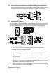
2 Installation
The DST-2000C is supplied in an industrial, painted steel housing which is designed
to be installed within an enclosure. The DST-2000C can be mounted horizontally or
vertically depending on the specific application conditions. A space of 6¼ X 11¼
inches allows for a minimum 1½ inches of clearance for ease of access needed for
terminal connections and servicing. The system installation should comply with all
appropriate electrical codes and standards.
2.1 Tools and Hardware
Required Tools Required Hardware
Screwdriver Four (4) 10-32 screws
Drill Four (4) #10 lock washers
#21 drill bit
10-32 tap
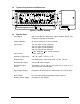
2.2 DST-2000C Terminals
Terminal Connect To
1 115 Vac (Hot) input or 220 Vac, optional
2 115 Vac (neutral) input or 220 Vac, optional
3 +12 Vdc input or +24 Vdc, optional
4 –12 Vdc (Common) input or –24 Vdc, optional
5 Regulated + 8 Vdc output
6 Square wave frequency output (Hi)
7 Square wave frequency output (Lo)
8 No connection
9 Input from M343 (White lead from C917-10)
10 Input from M343 (Blue lead from C917-10)
11 No connection
12 Input from M343 (Green lead from C917-10)
13 Input from M343 (Brown lead from C917-10)
14 CCW Relay NO contact output
15 CCW Relay Common output
16 CCW Relay NC contact output
17 CW Relay NO contact output
18 CW Relay Common output
19 CW Relay NC contact output
20 Anode for external LED output
21 Cathode for CW LED output (10 mA)
22 Cathode for CCW LED output (10 mA)
23 0–1 mA meter output (+)
24 0–1 mA meter output (–)
25 CW +8 V, 35 microsecond, pulse output
26 CCW +8 V, 35 microsecond, pulse output