DST-2000C Direction Sensing Tachometer INSTRUCTION MANUAL Azonix-Dynalco, 3690 N. W. 53 Street, Ft. Lauderdale, FL 33309 U.S.A. ! (954) 739-4300 • Fax (954) 484-3376 www.dynalco.com • mailbox@dynalco.
October 1999 This document contains information on a new product. Specifications and information herein are subject to change without notice. Dynalco Controls reserves the right to make changes to the equipment described herein to improve function or design. Although the information contained in this manual has been carefully reviewed and is believed to be reliable, Dynalco Controls does not assume any liability arising out of the application or use of the equipment described herein.
Table of Contents Overview ..............................................................................................................5 1 Product Description.....................................................................................5 1.1 Features .....................................................................................................5 1.2 Functional Description ................................................................................5 1.
BLANK PAGE 4 DST-2000C Instruction Manual
DST-2000C INSTRUCTION MANUAL Overview The purpose of this manual is to provide the users with the information necessary to install and operate the DST-2000C™ Direction Sensing Tachometer. 1 Product Description The DST-2000C operates with the M343 dual output magnetic pickup to detect the direction of rotation, and provides outputs to indicate direction and speed. (The older M917 pickup is no longer manufactured. This pickup ONLY works with the DST-2000B.) 1.1 Features • • • • • • 1.
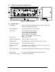
1.3 Terminal Connections and Dimensions Figure 1-1 Outline Drawing 1.4 6 Specifications Input Signal: Signal from Dynalco M343 dual output magnetic pickup only. Frequency range 0.5 Hz to 20 kHz. Signal Amplitude: 25 mVrms minimum; 15 Vrms maximum. Input Power: 115 Vac and/or 12 Vdc (standard)* 115 Vac and/or 24 Vdc (optional)* 230 Vac and/or 12 Vdc (optional)* 230 Vac and/or 24 Vdc (optional)* *+10%, 50/60 Hz, +10%, 2 watts maximum Input Current: 2 watts, maximum.
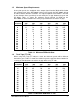
1.5 Minimum Speed Requirements At very low speeds, the amplitude of the output signal from the M343 will be below the sensitivity level of the DST-2000C. At these low speeds the DST-2000C will not be able to detect direction of rotation. The output amplitude of the M343 is affected by the diameter of the gear being sensed and by the air gap between the gear and the M343.
2 Installation The DST-2000C is supplied in an industrial, painted steel housing which is designed to be installed within an enclosure. The DST-2000C can be mounted horizontally or vertically depending on the specific application conditions. A space of 6¼ X 11¼ inches allows for a minimum 1½ inches of clearance for ease of access needed for terminal connections and servicing. The system installation should comply with all appropriate electrical codes and standards. 2.1 2.
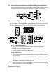
2.3 Wiring Connections Between DST-2000C & M343 Pickup Connector Wiring connections between the DST-2000C and the M343 magnetic pickup connector C917-X (X = length of connector cable in inches) are as follows: 2.4 Calibration Procedure The only calibration to the DST-2000C recommended by the factory is calibration of the 0–1 mA Meter Output. {Note: The two potentiometers on the bottom of the PC board are factory adjustments only and no user adjustment should attempted.} 2.4.
2.4.3 Calibration • Turn the F-16 power on and verify the Count/Generate switch is in the Generate position. • Adjust the F-16 to the full-scale frequency as required by the application. To compute the full-scale frequency, multiply (the number of discontinuities sensed) by (the maximum speed) and divide by 60. Hertz (frequency) = Number of Gear Teeth X RPM divided by 60 • Connect power source to DST-200C • Turn power on to the DST-2000C. • Verify that the CW relay energizes.
BLANK PAGE DST-2000C Instruction Manual 11
DST-2000C Instruction Manual