
Manual
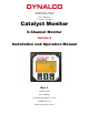


3
Flash Memory:
The onboard flash memory is sufficient to hold up to 500,000 data values with date / time
stamp. When the Catalyst Monitor receives an engine run signal (either contact closure or
mag pickup signal) the unit begins monitoring all enabled inputs. Following that, the monitor
will begin logging data as configured. The logged data is temporarily saved to RAM memory
which holds 56 logged values. The logged values remain in RAM until any of (3) events
occur:
1) The RAM is full.
2) The monitor receives an engine stop signal.
3) The user initiates a “Stop Logging” command.
Following any of the above events, the data in RAM is transferred to the non-volatile flash
memory. These values can be downloaded at any time to a PC using Dynalco’s download
cable and Log Reader software.
IMPORTANT - Input Power Requirements:
It is important that the input supply power be a reliable source with battery backup if needed.
If input power is interrupted or disconnected while the monitor is logging data, any data that
has not yet been stored to flash memory may be lost. This manual contains information on
page 14 that describes the steps required to safely disconnect power without risk of losing
data.
Additional Features
• 5 - Digit Hourmeter Function (non-resettable)
• Engine RPM Display
• Fully programmable from front keypad
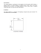
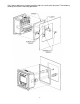
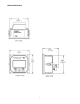
• ¼ DIN package (3 ½” width X 3 ½” height) for panel mount
Specifications
Input Types J or K type thermocouple (ungrounded) accurate to +/- 0.2 %
4 - 20 mA
0 – 1 VDC
0 - 5 VDC
0 – 10 VDC
Digital Input Closure to ground indicates run condition (or use pulsed input)
Pulsed Input Magnetic pickup input for RPM display & to indicate run condition
Relay Outputs 2 Digital Outputs rated @ 0.15 A / 48 VDC
Input Power 10 – 36 VDC
Display Backlit Graphic Display
Data Logging Internal Flash Memory to retain data logged values w/ date & time stamp
Communications Modbus
Connections Two-Part Terminal Blocks
Operating Temperature Range - 40 to + 70 Deg C
Certification CSA Class I, Division 2, Groups A, B, C, D