L Series and C Series FIR-Drive Power Amplifiers en | Installation manual
L Series and C Series FIR-Drive Power Amplifiers Table of Contents | en 3 Table of contents 1 Safety 5 1.1 Safety messages explained 5 1.2 Important safety instructions 5 1.3 Safety precautions 7 1.4 FCC 8 1.5 Notices 8 2 About this manual 9 2.1 Manual purpose 9 2.2 Digital document 9 2.3 Intended audience 9 2.4 Short Information 9 3 System overview 11 3.1 Application area 11 3.2 Features 11 3.3 Unpacking and inspection 11 3.
L Series and C Series FIR-Drive Power Amplifiers en | Table of Contents 8.3 Block diagrams 38 8.4 Dimensions 40 2017.10 | 02 | F.01U.327.
L Series and C Series FIR-Drive Power Amplifiers Safety | en 1 Safety 1.1 Safety messages explained 5 Four types of signs can be used in this manual. The type is closely related to the effect that may be caused if it is not observed. These signs - from least severe effect to most severe effect - are: Notice! Containing additional information. Usually, not observing a ‘notice’ does not result in damage to the equipment or personal injuries.
L Series and C Series FIR-Drive Power Amplifiers en | Safety 5. Do not operate the device in close proximity to water. 6. Use only a dry cloth to clean the unit. 7. Do not cover any ventilation slots. Always refer to the manufacturer's instructions when installing the device. 8. Do not install the device close to heaters, ovens, or other heat sources. 9. Note: The device must only be operated via the mains power supply with a safety ground connector.
L Series and C Series FIR-Drive Power Amplifiers 3. Safety | en 7 The device must be free of any voltage before performing any alterations with upgrade sets, switching the mains voltage, or performing any other modifications. 4. The minimum distance between voltage-carrying parts and metal parts that can be touched (such as the metal housing) or between mains poles is 3 mm, and must be observed at all times. 5.
1.4 L Series and C Series FIR-Drive Power Amplifiers en | Safety FCC IMPORTANT: Do not modify this unit! Changes or modifications not expressly approved by the manufacturer could void the user’s authority, granted by the FCC, to operate the equipment. Notice! This equipment has been tested and found to comply with the limits for a Class B digital device, pursuant to Part 15 of the FCC Rules.
L Series and C Series FIR-Drive Power Amplifiers About this manual | en 2 About this manual 2.1 Manual purpose 9 The purpose of this manual is to provide information required for installing, configuring, operating and maintaining the L Series FIR-Drive Power Amplifier and C Series FIR-Drive Power Amplifier hardware products. Read through this manual to familiarize yourself with the safety information, features, and applications before you use these products. 2.
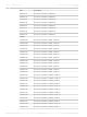
L Series and C Series FIR-Drive Power Amplifiers en | About this manual CTN Description L2800FD-UK DSP power amplifier 2x1400W UK L2800FD-US DSP power amplifier 2x1400W US L3600FD-AU DSP power amplifier 2x1800W AU L3600FD-CN DSP power amplifier 2x1800W CN L3600FD-EU DSP power amplifier 2x1800W EU L3600FD-JP DSP power amplifier 2x1800W JP L3600FD-UK DSP power amplifier 2x1800W UK L3600FD-US DSP power amplifier 2x1800W US C Series C1300FDi-AU DSP power amplifier 2x650W, install AU C1
L Series and C Series FIR-Drive Power Amplifiers System overview | en 3 System overview 3.1 Application area 11 The L Series and C Series power amplifier are designed to power professional loudspeaker system in live and fix installed audio applications such as concerts, clubs, sports venues, HOWs and many other applications. 3.
L Series and C Series FIR-Drive Power Amplifiers en | System overview Quantity Component 1 Installation manual 1 Safety instruction card Table 3.1: L Series Quantity Component 1 DSP amplifier 1 Mains cord 1 USB cable 1 Euroblock GPIO connector 6 pole 1 Euroblock output connector 4 pole 2 Euroblock input connectors 3 pole 1 Power remote connector 2 pole 1 Installation manual 1 Safety instruction card Table 3.
L Series and C Series FIR-Drive Power Amplifiers 4 Planning information | en 13 Planning information Ensure the following: • You make use of manufacturer specified installation materials. • No liquids can spill into or on the products. • Installation is in a clean environment free of dust. • The ventilation airflow of the 19" units is not obstructed. • There is a mains power outlet of sufficient rating close to the intended location of the products.
L Series and C Series FIR-Drive Power Amplifiers en | Installation 5 Installation 5.1 Operating voltage The power amplifier receives its power supply via the MAINS IN connector. Only the provided power cord may be used. During installation, always separate the power amplifier from the mains. Connect the power amplifier only to a mains network, which corresponds to the requirements indicated on the type plate. 5.2 Power The L Series power button is located on the front of the amplifier panel.
L Series and C Series FIR-Drive Power Amplifiers 5.3 Installation | en 15 Mounting L Series and C Series amplifiers have been designed for installation in a conventional 19-inch rack case. Attach the power amp with its frontal rack mount ears using four screws and washers as shown in the illustration. Additionally securing the amplifier at the rear becomes necessary, if the rack case in which the power amplifier has been installed will be transported.
L Series and C Series FIR-Drive Power Amplifiers en | Installation Caution! ! Blocking/closing the power amp's ventilation louvers is not permissible. Without sufficient cooling/ventilation, the power amplifier may automatically enter protect mode. Keep ventilation louvers free from dust to ensure unhindered airflow. Notice! Do not use the power amplifier near heat sources, like heater blowers, stoves, or any other heat radiating devices.
L Series and C Series FIR-Drive Power Amplifiers Controls, indicators and connections | en 6 Controls, indicators and connections 6.1 L Series amplifier 17 Front view 2 1 3 1. LCD - LCD control and monitoring interface. 2. Encoder knob - Scroll through the DSP menu and select the available choices. Push the encoder knob to enter the DSP menu. 3. POWER - AC button for turning the power ON or OFF. The LCD screen lights up when the power is turned on.
L Series and C Series FIR-Drive Power Amplifiers en | Controls, indicators and connections C Series amplifier 6.2 Front view 1 2 3 4 1. LCD - LCD control and monitoring interface. 2. Encoder knob - Scroll through the DSP menu and select the available choices. Push the 3. POWER - Power on/off indicator. 4. STANDBY - standby indicator. encoder knob to enter the DSP menu.
L Series and C Series FIR-Drive Power Amplifiers 6.4 Controls, indicators and connections | en 19 Groundlift The ground lift switch allows eliminating hum noise loops. When operating the power amplifier together with other equipment in a rack case, setting the switch to the GROUNDED position is recommended. Set the switch to UNGROUNDED, when the power amplifier is operated together with appliances with differing ground potentials. 6.
L Series and C Series FIR-Drive Power Amplifiers en | Controls, indicators and connections GPI: The GPI is used to change between two internal device presets. If the GPI 1 or GPI 2 is set to GND potential, the preset is switched from the original selected preset to the preset set for GPI 1 or GPI 2. GPO: The GPO is designed as a potential-free changeover switch (relay). If power is on, GPO pin 3 and GPO pin 1 are shorted.
L Series and C Series FIR-Drive Power Amplifiers Controls, indicators and connections | en 21 Cabling with Speakon-type connector in Bridged mode In Bridged mode both amp channels work in push-pull operation to provide doubled output voltage. In bridged mode operation speaker connection has to be established using pins 1+ and 2- of the Speakon socket CHANNEL A. The correct connection is also indicated at the amplifiers rear panel. Figure 6.
L Series and C Series FIR-Drive Power Amplifiers en | Controls, indicators and connections In Bridged mode operation speaker connection has to be established using pins 1+ and 2-, see illustration. The correct connection is also indicated at the amplifiers rear panel. Figure 6.5: Bridged mode Caution! In Bridged mode operation, it is not allowable for the load connected to all below a value of 4 ohms. Extremely high voltages can be present at the output.
L Series and C Series FIR-Drive Power Amplifiers Controls, indicators and connections | en 23 2, HOT 3, COLD JUMPER FROM COLD TO SHIELD Figure 6.7: Unbalanced connection of input Next to its input connector, each channel provides an individual XLR-type connector (OUTPUT A or OUTPUT B), which is connected in parallel to allow for comfortably daisy-chaining the audio signal for the connection of additional audio equipment. 1, SHIELD 3, COLD 2, HOT Figure 6.
L Series and C Series FIR-Drive Power Amplifiers en | Power amplifier menu navigation 7 Power amplifier menu navigation 7.1 Amplifier and DSP control An integrated amplifier and DSP control menu allows the user to select multiple system settings on the power amplifier. When the power amplifier is powered on the home screens appears. Figure 7.
L Series and C Series FIR-Drive Power Amplifiers Preset Power amplifier menu navigation | en F1 --- F8/10** Load Preset U1 --- U50 Last F1 -- F8/10* U1 --- U50 Store Preset Startup: AMP Setup DSP Edit GPI Config* Bridged Routing A: Normal In A Routing B: In B In A In B In A+B Mode: EQ A EQ B U1 --- U50 ** See preset table In A In B In A+B EQ 1-5: Enable (On/Off), Type (PEQ, Loshelv, Hishelv, Hipass, Lopass), Frequency (20Hz - 20kHz), Gain (-18dB - +12dB), Quality (0.4 - 40.
L Series and C Series FIR-Drive Power Amplifiers en | Power amplifier menu navigation Notice! Controlling multiple amplifiers via Dynacord control software: It is recommend to use a powered USB hub if the user wishes to control amplifiers with one cable to their computer. USB range extenders can also be used to remotely position the software control interface longer distances from the amplifiers.
L Series and C Series FIR-Drive Power Amplifiers F08 Power amplifier menu navigation | en Name Input Routing 70V Single In A > Out A&B Bridged Mode! Hi-Pass 18dB @ 50Hz 27 Parameters C1800FDi F08 70V Dual In A > Out A In B > Out B Hi-Pass 18dB @ 50Hz F09 70V Mono In A > Out A In A > Out B Hi-Pass 18dB @ 50Hz F10 100V Single In A > Out A&B Bridged Mode! Hi-Pass 18dB @ 50Hz C2800FDi and C3600FDi F08 70V Dual In A > Out A In B > Out B Hi-Pass 18dB @ 50Hz F09 70V Mono In A > Out
L Series and C Series FIR-Drive Power Amplifiers en | Power amplifier menu navigation Lock menu: Restricts unauthorized access by locking access to the amplifier in different options. Using the lock feature affects changes to Front Control, Preset, AMP Setup, DSP Edit, USB and Reset function with a 4-digit pin code. Use the encoder knob to view the menu/ function you want to lock. Notice! Keep your password in a safe place.
L Series and C Series FIR-Drive Power Amplifiers 8 Technical data | en 29 Technical data Amplifier model Load Impedance L1300FD/C1300FDi 2Ω 2.6 Ω 4Ω 8Ω Maximum Output Power, Single Channel 1100 W 950 W 660 W 350 W Maximum Output Power, Dual Channel 1000 W 850 W 600 W 320 W - - 2000 W 1200 W Maximum Output Power, Bridged Maximum RMS Voltage Swing 55.3 V THD = 1%, 1 kHz Voltage Gain 32.0 dB Ref.1 kHz THD at 450 W/4 Ω < 0.05% MBW = 80 kHz, 1 kHz IMD-SMPTE, < 0.
L Series and C Series FIR-Drive Power Amplifiers en | Technical data Amplifier model L1300FD/C1300FDi Color Black Dimensions (W x H x D), mm 483 x 88 x 462.4 Weight 12.9 kg (28.
L Series and C Series FIR-Drive Power Amplifiers Technical data | en Amplifier model 31 L1800FD/C1800FDi Signal to Noise Ratio Amplifier, >105 dB A-weighted, ref to Max.
L Series and C Series FIR-Drive Power Amplifiers en | Technical data Amplifier model L2800FD/C2800FDi Voltage Gain 32.0 dB Ref.1 kHz THD at 900 W/4 Ω < 0.05% MBW = 80 kHz, 1 kHz IMD-SMPTE, < 0.1% 60 Hz, 7 kHz DIM30, < 0.05% 3.15 kHz, 15 kHz Maximum Input Level +21 dBu Crosstalk < -80 dB ref. 1 kHz, at 100 W/4 Ω Frequency Response, 10 Hz to 21 kHz (±1 dB) ref. 1 kHz Input Impedance, 20 k Ω Active Balanced Signal to Noise Ratio Amplifier, >107 dB A-weighted, ref to Max.
L Series and C Series FIR-Drive Power Amplifiers Technical data | en Amplifier model 33 L2800FD/C2800FDi Signal Processing FIR Filters, Audio Limiters Output delay per channel, 31 band GEQ per channel, PEQ per channel, Load impedance Accessories RMK15 (rear rack mount kit), Multi Amplifier Remote Control (MARC) software Test signal for max. output power according IHF-A-202 (Dynamic-Headroom, burst 1 kHz/20 ms on/480 ms off/low level -20 dBu). Amplifier model Load Impedance L3600FD/C3600FDi 2Ω 2.
L Series and C Series FIR-Drive Power Amplifiers en | Technical data Amplifier model L3600FD/C3600FDi Power Consumption 850 W 1/8 Maximum Output Power @ 4 Ω Mains Fuse 240 V/230 V: T15AH; 120 V/100 V: T30AH Protection Audio limiters, high temperature, DC, HF, Back-EMF, Peak current limiters, Inrush current limiters, Turn on delay Cooling Front-to-rear, 3-stage-fans Ambient Temperature Limits +5°C to +40°C (40°F to +105°F) Safety Class I Color Black Dimensions (W x H x D), mm 483 x 88
L Series and C Series FIR-Drive Power Amplifiers Technical data | en Model Load Capability Dual Channel Load Capability Bridge Mode C1800FDi 2 x 1250 W Not 1 x 1250 W recommended1 (-1.5 dB) 1 x 625 W Not available2 Not available2 (-1.5 dB) C1300FDi Not available2 35 (0.0 dB) Table 8.1: C Series direct drive load capability 1 This operation mode is not recommended due to the efficiency reasons. Please use the next smaller amplifier for this mode.
L Series and C Series FIR-Drive Power Amplifiers en | Technical data C1300FDi mains U Output Power I mains(5) mains P P out Pd(4) BTU/hr(3) [V] [A] [W] [W] [W] Rated Output Power @ 4Ω(1) 230 7.6 1400 2 x 400 600 2047 1/8 70V/625W (8Ω) Bridged 230 2.7 438 1 x 78 360 1228 P out Pd(4) BTU/hr(3) Mode(2) Table 8.2: C1300FDi power consumption C1800FDi mains U I mains(5) mains P Output Power [V] [A] [W] [W] [W] Idle 230 0.4 51 - 51 174 1/8 Max.
L Series and C Series FIR-Drive Power Amplifiers Technical data | en C2800FDi mains U Output Power 1/8 70V/2500W (4Ω) Dual I mains(5) mains P P out Pd(4) 37 BTU/hr(3) [V] [A] [W] [W] [W] 230 7.9 1344 2 x 313 718 2449 230 3.2 492 1 x 156 336 1146 P out Pd(4) BTU/hr(3) Channel (2) 1/8 100V/1250W (8Ω) Bridged Mode (2) Table 8.4: C2800FDi power consumption C3600FDi mains U I mains(5) mains P Output Power [V] [A] [W] [W] [W] Idle 230 0.
8.3 L Series and C Series FIR-Drive Power Amplifiers en | Technical data Block diagrams Figure 8.1: L Series amplifier block diagram 2017.10 | 02 | F.01U.327.
L Series and C Series FIR-Drive Power Amplifiers Technical data | en 39 Figure 8.2: C Series amplifier block diagram Bosch Sicherheitssysteme GmbH Installation manual 2017.10 | 02 | F.01U.327.
L Series and C Series FIR-Drive Power Amplifiers en | Technical data 8.4 Dimensions 438 mm [17.24”] 483 mm [19.02”] 462.4 mm [18.20”] 88 mm [3.47”] 462.4 mm [18.20”] 462.4 mm [18.20”] 418.2 mm [16.47”] 438 mm [17.24”] Figure 8.3: L Series and C Series amplifier dimensions (L Series shown) 2017.10 | 02 | F.01U.327.
Bosch Security Systems, Inc. 130 Perinton Parkway Fairport, NY 14450 USA www.dynacord.com © Bosch Security Systems, Inc.