
Power Supply User Manual

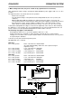

1.) covered mains switch
2.) mains LED-indicator (off, when the mains switch is not engaged)
3.) battery LED-indicator (off, when the mains switch is not engaged)
4.) mains input connector
5.) mains fuse (input connector)
6.) mains output connector
7.) mains fuse (output connector)
8.) ground-lift switch
9.) DC-output via flat-connector: +24 V / 4 A (DPP4004) or +24 V / 12 A (DPP4012) direct / GROUND
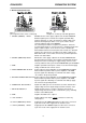
10.) remote control connector – for pin-assignment refer to diagram 1
11a.) battery fuse – input – negative pole
11b.) battery fuse – input – positive pole
12.) battery flat-connector – input – negative pole
13.) battery flat-connector – input – +24 VDC
14.) DC-output via flat-connector: +24 V / 4 A (DPP4004) or +24 V / 12 A (DPP4012) switched
15.) DC-output via flat-connector – negative pole
16.) DC-output via flat-connector for the PROMATRIX SYSTEM; persistent power supply
17.) ventilation louvres – airflow in
18.) ventilation louvres – airflow out
DYNACORD PROMATRIX SYSTEM
14