OWNER‘S MANUAL BEDIENUNGSANLEITUNG MODE D‘EMPLOI CMS 1000/1600/2200 COMPACT MIXING SYSTEM
CONTENTS SAFETY- AND SERVICE INSTRUCTIONS IMPORTANT SAFETY INSTRUCTIONS IMPORTANT SERVICE INSTRUCTIONS DESCRIPTIONS UNPACKING AND WARRANTY INSTALLATION AND CONNECTIONS INPUT MONO INPUT STEREO EFFECT 1/2 AUX3&4 MASTER REAR PANEL CABLING SETTING UP A STANDARD-PA SYSTEM SETUP EXAMPLES SPECIFICATIONS BLOCK DIAGRAM DIMENSIONS ....................... ....................... ....................... ....................... ....................... ....................... ....................... ....................
IMPORTANT SAFETY INSTRUCTIONS The lightning flash with arrowhead symbol, within an equilateral triangle is intended to alert the user to the presence of uninsulated „dangerous voltage“ within the product’s enclosure that may be of sufficient magnitude to constitute a risk of electric shock to persons. The exclamation point within an equilateral triangle is intended to alert the user to the presence of important operating and maintance (servicing) instructions in the literature accompanying the appliance. 1.
DESCRIPTIONS In a world of plethora and mass production, quality, functionality and design are more important than ever. We at DYNACORD design and manufacture first-class products – “Made in Germany”– that provide positive experiences through real worldoptimized detail solutions. They are built to please you for a long time. The highest degree of customer satisfaction is our supreme ambition.
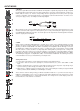
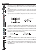
INPUT MONO 1. MIC Electronically balanced XLR-type inputs for the connection of low impedance microphones like the ones featured in state-of-the-art studio and live mixing consoles. This type of input stage provides extraordinary low noise signal conversion at an extremely low distortion rate (typical <0.002%) even in the high frequency range. Generally, any type of microphone can be connected as long as its pin assignment is in accordance to the diagram as shown below.
INPUT MONO 3. INSERT Stereo phone jack with breaker function and with the low impedance output being assigned to the tip (send) and the high impedance input (return) to the ring. This jack allows the connection of external FX units, compressors, limiters, EQs, de-noisers, etc. into the corresponding channel’s signal path. The insertion point is post gain controls, Lo-Cut filters, and voicing stage but pre sound shaping section and channel faders.
INPUT MONO 5. LO CUT 80 Hz When the LO CUT switch is engaged, frequencies below 80 Hz are 5 attenuated (18dB octave slope). In most cases it is good advice to 0 use the LO CUT filter with microphone channels, since it efficiently -5 suppresses popping sounds, rumbling noise and low-frequency -10 feedback. The only exceptions are kick drum and bass.
INPUT MONO Adjustments in the MID frequency range are certainly the most effective way to shape the sound. As a matter of fact, determining the correct center frequency is not always as easy as it seems. Here is one method – amongst others – how to quickly find the right setting of the parametric EQ for your application: Setting Instructions: 1. Slightly lower the channel fader to avoid feedback. 2. Position the MID rotary control in the range of +9dB … +15dB. 3.
INPUT MONO 10. PAN This control determines the position of the connected sound source within the stereo image. When the control is set at its center position, the audio signal is fed with equal levels to the L and R master busses. The PAN control section is designed to maintain the essential sound pressure level, no matter at what position within the stereo image the PAN control is set to. 11. MUTE The MUTE button mutes the input signal post fader, including all AUX sends.
INPUT STEREO Since most features – AUX controls, input connection and channel faders – of the STEREO INPUTS are virtually identical to the ones of the MONO INPUTS we will not discuss their functioning in detail again. Thus, in the following we only point out the differences and like to ask you to refer to the analogous paragraphs within this owner’s manual describing the MONO INPUTS. 15.
INPUT STEREO 18. LINE TRIM Control for matching incoming line level signals to the mixer’s operating level. The total adjustment range is 30dB. Unity gain – no amplification (0 dB) – is achieved at the 0dB mark. The control offers level reduction of –10dB or amplification of +20dB. This range allows the connection of most professional, semi professional, and hi-fi sound sources. For further details on how to set the LINE TRIM control, please refer to the description of gain controls in monaural channels.
INPUT STEREO 23. MUTE The MUTE button mutes the input signal post fader, including all AUX sends. PFL and Signal/Peak stay operational. 24. PFL Engaging the PFL button sums the stereophonic audio signal of the corresponding input channel and routes the resulting monaural signal to the headphones bus. You are able to listen to the audio signal via the phones output.
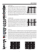
EFFECTS 1/2 FX1/FX2 The CMS offers two independently controllable, identically configured 24-bit stereo effect units – FX1 and FX2. Each unit provides 99 program presets, which can be selected by means of the UP/DOWN buttons. The 99 presets are divided into groups according to their different effect structure, as printed on the CMS and shown in the following listing. FX1/FX2 1.......10 11.......20 21......30 31......40 41......50 51......60 61......
EFFECTS 1/2 29. DISPLAY The display always indicates the actual selected program number of the corresponding FX unit. The display screen is covered with a protective foil to prevent it from being damaged during shipment. Please remove the foil. 30. UP/DOWN The UP/DOWN buttons are for selecting effect presets. Pressing and holding one of these lets you scroll through the program numbers. 31/32. FX1/2 to AUX3/4 These controls allow adding the output signal of FX1 or FX2 to the monitoring channel.
AUX3&4 / MASTER Generally, the AUX3/4 channel is used for monitoring purposes. Depending on the setting of the AUX3/4 POST buttons, it is also possible to configure the bus for the connection of an additional, external FX unit. 37. AUX3/4 OUT This output provides connection for monitor power amplifiers, active speaker systems or external FX units. Using the AUX3/4 fader allows setting the output level of this electronically balanced output in a wide range up to +20dBu.
AUX3&4 / MASTER 42. PFL Through this button you can route the pre AUX3/4 fader signal to the headphones bus. The signal is outputted for listening via the headphones output. The setting of the AUX3/4 fader is not relevant for the signal’s volume (PRE FADER LISTEN). The meter instrument in the master section is simultaneously switched, so that the left LED-chain indicates the level (in dBu) of the actually chosen AUX channel. 43.
MASTER 46. MASTER LED-DISPLAY The CMS offers two 12-segment LED-chains for indication of left and right channel output levels. The indication range of the LED-meter is 40dB, indicating the levels (in dBu) that are present at the master outputs. The meter’s 0dB mark is referenced to a 0dBu output signal at the mixer output. Please mind that the signal indicated by the Master LED display is pre equalizer.
MASTER 51. MONO OUTPUT At this electronically balanced monaural output the summed L/R master audio signal is present and can be used for additional monitoring, side fill and “next door” or Mono-PA applications as well as for the connection of a delay-line or subwoofer. The MONO OUTPUT – like any other XLR-type outputs on the CMS – is switched via output relay with a delay of approx. two seconds after the mixer has been powered on, which prevents power-on noise when switching the mixer on or off. 52.
MASTER 57. 2TRACK to MASTER This control is used to add the 2TRACK signal to the main mix; post fader of the master controls. Caution: When setting the level of the device that is connected to the 2TRACK RETURNS – e. g. CD player, tape deck, etc. – always begin with the 2TRACK to MASTER control set at its minimum setting; all the way counterclockwise. Otherwise, depending on the output quality of the connected sound source, the outputted level can instantly “hit the top”. 58.
REAR PANEL POWER Mains switch to turn the CMS on or off. The CMS is operational once the POWER LED lights and outputs are activated through automatic switching of the output relays. Please make sure to set the master faders to their minimum position or engage the STANDBY switch before switching the power on. This will save you, your audience, and the equipment from unnecessary stress from unwanted loud signals or even worse from acoustic feedback.
CABLING Cabling The mains cord comes with the CMS. The quality of all other cables lies in your responsibility. Carefully chosen high quality cables are the best precaution to prevent later problems during live operation. The following wiring alternatives are recommended to provide trouble free operation of your system.
SETTING UP A STANDARD-PA SYSTEM • • • • • • • • • • • Place the CMS and all connected appliances in a way that allows their unobstructed operation and connect the mains cord. Try to locate the best position where you want to place the main PA loudspeaker systems. If possible, the woofers should be placed on the floor while the Hi cabinets’ most favorable position is above the Lo cabinets, on the same vertical axis.
SETTING UP A STANDARD-PA SYSTEM Main Mix Position the master faders in the range between –30dB and –20dB. • Use the channel faders to establish a basic mix, so that individual sound levels relate to each other according to your personal taste. • The best range for the channel faders to be set to is in the area of –5dB to 0dB. In this way you are provided with enough tolerance for later adjustment. • Use the master faders to set the overall volume of the main PA.
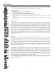
SETUP EXAMPLES Optional Subwoofer Monitoring Setting up a sound reinforcement system with active components.
SETUP EXAMPLES Monitoring Setting up a sound reinforcement system with active components.
SETUP EXAMPLES Monitoring Setting up a sound reinforcement system with power amps.
WICHTIGE SICHERHEITSHINWEISE Das Blitzsymbol innerhalb eines gleichseitigen Dreiecks soll den Anwender auf nicht isolierte Leitungen und Kontakte im Geräteinneren hinweisen, an denen hohe Spannungen anliegen, die im Fall einer Berührung zu lebensgefährlichen Stromschlägen führen können. Das Ausrufezeichen innerhalb eines gleichseitigen Dreiecks soll den Anwender auf wichtige Bedienungssowie Servicehinweise in der zum Gerät gehörenden Literatur aufmerksam machen. 1. 2. 3. 4. 5. 6. 7. 8. 9. 10. 11. 12. 13.
BESCHREIBUNG In der Welt des Überflusses und der Massenproduktion sind mehr denn je Qualität, Funktionalität und Design entscheidende Faktoren. Wir aus dem Hause DYNACORD entwickeln und produzieren, „Made in Germany“, erstklassige Produkte, die durch praxisoptimierte Detaillösungen positive Erlebnisse vermitteln und Ihnen im täglichen Gebrauch lange Freude bereiten. Höchstmögliche Zufriedenheit der Kunden ist unser oberstes Gebot.
INPUT MONO 1. MIC Elektronisch symmetrische XLR-Eingänge zum Anschluß niederohmiger Mikrofone, wie sie auch in großen Studio- oder Livekonsolen verwendet werden. Diese Art der Eingangsstufe ist extrem rausch- und brummarm, darüberhinaus weist sie einen äußerst niedrigen Klirrfaktor (typ.<0.002%), auch bei hohen Frequenzen auf. Sie können hier im Prinzip jedes Mikrofon anstecken, sofern Sie dabei auf die Pin-Belegung entsprechend der untenstehenden Abbildung achten.
INPUT MONO 3. INSERT Stereo-Klinkenbuchse mit Unterbrechungs-Funktion, die mit einem niederohmigen Ausgang (Send) an der Spitze (Tip) und einem hochohmigen Eingang (Return) am Ring belegt ist. Diese Buchse ermöglicht das Einschleifen von externen Effektgeräten wie Kompressor, Limiter, EQ, De-Esser, usw. in den jeweiligen Kanal. Der Einschleifpunkt liegt schaltungstechnisch nach der Gain-, LO-Cut- und Voicing Stufe, also noch vor der Klangregelung und dem Kanalschieberegler.
INPUT MONO 5. LO CUT 80 Hz Mit dem LO CUT Schalter können Baßfrequenzen unterhalb 80 Hz mit einer Flankensteilheit von 18 dB pro Oktave unterdrückt werden. Sinnvoll ist die Benutzung des LO CUT-Filters vor allem bei allen Mikrofonanwendungen, wobei hier die Abnahme von Bassdrum oder Bass gesondert zu betrachten ist. Mit diesem Filter werden wirkungsvoll alle Rumpel- oder Poppgeräusche als auch tieffrequente Feedbacksignale unterdrückt.
INPUT MONO Im Mittenbereich können Sie am effektivsten Einfluß auf das Klangbild nehmen, wobei sich aber das Auffinden der optimalen Arbeitsfrequenz mit dem Frequenzsteller nicht immer ganz einfach gestalltet. Darum hier eine Möglichkeit (unter vielen) wie Sie schnell eine für Ihre Anwendung passende Einstellung des parametrischen EQs finden. Einstellhinweis: 1. Ziehen Sie den Kanalfader etwas zu, um etwaige Rückkopplungen zu vermeiden. 2. Stellen Sie den MID-Regler nach rechts auf 9dB....15dB. 3.
INPUT MONO 10. PAN Dieser Regler bestimmt die räumliche Position des Eingangssignals im Stereobild. In Mittelstellung wird das Signal zu gleichen Teilen auf die beiden Summen L und R aufgeteilt. Die PAN-Regler Stufe ist so ausgelegt, dass egal wo Sie den PAN-Regler hindrehen, die Gesamtlautstärke im Stereo Klangbild erhalten bleibt. 11. MUTE Die MUTE-Taste schaltet das Eingangssignal ab dem Kanalschieberegler, einschließlich aller AUX-Sends stumm. PFL und Signal/Peak funktionieren weiterhin. 12.
INPUT STEREO Wir wollen Sie hier bei der Beschreibung des STEREO-INPUTS nicht langweilen, viele Funktionsgruppen wie AUX-Regler, Eingänge, Kanalfader im STEREO INPUT sind identisch zum MONO INPUT aufgebaut und wurden dort bereits ausführlich erklärt. Wir wollen hier nur die wesentlichen Unterschiede herausarbeiten. Ansonsten dürfen wir Sie auf das jeweilige Kapitel beim MONO-INPUT verweisen. 15.
INPUT STEREO 18. LINE TRIM Mit diesem Regler wird das Signal an den Line-Eingängen im Stereokanal an den internen Arbeitspegel des Mischpultes angepaßt. Der Regelbereich liegt bei 30 dB. Die Unity Gain Position, also 0 dB Durchgangsverstärkung, ist hier bei der Markierung 0 dB. Sie können mit diesem Regler das Signal um 10 dB abschwächen bzw. um 20 dB verstärken. Der Regelbereich ist ausreichend um die meisten professionellen, semi-professionellen und HI-FI Quellen anzupassen.
INPUT STEREO 20. AUX / FX Mit diesen Reglern wird das aus L und R summierte Signal POST-FADE auf die AUX/FX-Summenschienen ausgespielt. Die Funktionsweise wurde bereits im INPUT/MONO erläutert. 21. AUX3/4 Legt das aus L und R summierte Signal auf die AUX3- bzw. AUX4 Summenschiene. Dies kann entweder POSTFADER oder PRE-FADER geschehen und wird wie im Monokanal über den AUX PRE/ POST Schalter im Masterbereich ausgewählt. Die Funktionsweise wurde bereits im Monokanal erläutert. 22.
EFFEKT 1/2 FX1/FX2 Das CMS ist mit zwei unabhängig voneinander regelbaren 24bit-Stereo-Effektteilen FX1 und FX2 ausgestattet. Die beiden Effektteile sind völlig identisch aufgebaut. Es stehen je Effektsektion 99 Preset-Stereo-Effektprogramme zur Auswahl, die mit den UP/DOWN Tasten selektiert werden. Die 99 Preset-Programme sind in Sektionen entsprechend der Effektstruktur eingeteilt, wie Sie an der aufgedruckten Tabelle erkennen können. FX1/FX2 1.......10 11.......20 21......30 31......40 41......
EFFEKT 1/2 29. DISPLAY Das Display zeigt immer die aktuell eingestellte Programmnummer des jeweiligen Effektteils an. Zum Schutz vor Verkratzen ist das Displayglas bei Auslieferung mit einer Folie abgedeckt. Ziehen Sie diese bitte ab. 30. UP/DOWN Mit den UP/DOWN-Tasten werden die Effektprogramme angewählt. Wenn Sie länger auf eine dieser Tasten drücken, können Sie dadurch eine schnellen Vor- bzw. Rücklauf der Programmnummern erzeugen. 31/32.
AUX3/4 Der AUX3/4-Kanalzug wird im wesentlichen zum Monitoring verwendet. Über die AUX3/4 POST Tasten, ist es aber auch möglich hier einen zusätzliches externes Effektgerät zu betreiben. 37. AUX3/4 OUT Hier schließen Sie eine Monitorendstufe bzw. einen Aktivmonitor oder ggf. ein Effektgerät an. Der Pegel an diesem elektronisch symmetrischen Ausgang kann in einem weitem Bereich bis maximal +20 dBu über den AUX3/4 Fader geregelt werden.
MASTER 42. PFL Diese Taste gibt das Signal, das vor dem AUX3/4-Fader steht, auf die Kopfhörersumme. Sie können dann das AUX3/4-Signal am Kopfhörerausgang abhören. Die Lautstärke am Kopfhörerausgang ist dabei unabhängig vom AUX3/4-Fader (PRE FADER LISTEN). Gleichzeitig bewirkt das Drücken des PFL-Schalters ein Umschalten der Aussteuerungsanzeigen im Master.
MASTER 46. MASTER LED-DISPLAY Die Aussteuerungsanzeige im CMS besteht aus zwei LED-Ketten für den rechten bzw. linken Kanal mit je 12 LEDs pro Kette. Der Anzeigebereich liegt bei 40 dB und stellt den Pegel in dBu an den Main Outputs dar. D.h. zeigt die Anzeige 0 dB an, so stehen am Mischpultausgang aktuell 0 dBu. Steuern Sie noch weiter aus, wird bei +6 dB der maximale Eingangspegel der internen Endstufe erreicht und die Endstufenblöcke liefern dann je 700 W an 4 Ohm.
MASTER 51. MONO OUTPUT Der elektronisch symmetrische Mono-Ausgang führt das summierte Master L/R Signal, und kann z.B. für Monitoring, Sidefill, Nebenraumbeschallung, Mono-PA oder zum Anschluß einer Delay-Line oder Subwoofer verwendet werden. Wie alle XLR Ausgänge des CMS wird auch der MONO OUTPUT über Ausgangsrelais ca. zwei Sekunden nach Einschalten des Geräts aktiviert. Knackgeräusche beim Ein- bzw. Ausschalten können somit nicht auftreten. 52.
MASTER 57. 2TRACK to MASTER Mit diesem Regler wird das 2TRACK Signal dem MASTER-Kanal POST-FADER zugemischt. Achtung: Gehen Sie beim Einpegeln des am 2TRACK RETURN angeschlossenen externen Gerätes wie z.B. CD-Player oder Tape-Deck immer vom Regler im Linksanschlag aus, da z.B. je nach Qualität der Aufnahme relativ schnell eine sehr hohe Endstufenausgangsleistung erzeugt werden kann. 58.
RÜCKSEITE POWER Netzschalter zum Ein- und Ausschalten des Gerätes. Das Gerät ist betriebsbereit, wenn die POWER LED aufleuchtet und die Ausgangsrelais das Signal auf die Ausgänge geschaltet haben. Achten Sie bitte darauf, daß beim Anschalten des Gerätes die beiden MasterSchieberegler geschlossen sind, oder die STANDBY-Taste gedrückt ist. Sie ersparen sich selbst, Ihrem Publikum und Ihrem Equipment unnötige Beanspruchungen durch ungewollte Signalverstärkung oder sogar Rückkopplungen.
AUFBAU EINER STANDARD-PA Verkabelung Das Netzkabel haben Sie mit dem CMS erhalten. Für alle anderen Kabel sind Sie selbst verantwortlich und je sorgfältiger Sie bei der Auswahl der Kabel vorgehen, um so weniger Probleme sind später im Einsatz zu erwarten. Wir können hier nur einige Empfehlungen geben mit denen Sie einen störungsfreien Betrieb Ihres Aufbaus erreichen.
AUFBAU EINER STANDARD-PA Aufbau • Stellen Sie das CMS und die angeschlossenen Geräte so auf, daß Sie auch im Betrieb leichten Zugriff haben und schließen Sie die Netzkabel an. • Suchen Sie die günstigste Position für Ihre PA-Boxen. Die Bassboxen sollen dabei immer unten am Boden stehen und die Hochtonboxen wenn möglich direkt darüber. Beachten Sie aber, daß die Unterkante der Hochtonboxen immer in Kopfhöhe ihres Publikums oder darüber ist.
AUFBAU EINER STANDARD-PA • Falls Sie an den Monokanälen Instrumente angeschlossen haben, verfahren Sie wie bei der Mikrofoneinstellung beschrieben • Überprüfen Sie nun, ob bei allen nicht benötigten Eingängen die Kanalfader und die Gain- bzw. LINE-TRIM-Regler geschlossen sind. Sie vermeiden dadurch unnötiges Rauschen auf den Ausgängen. Hauptmix • Dazu werden die Masterschieberegler auf ca. -30 ... -20 dB hochgezogen.
AUFBAU BEISPIELE Aufbau einer Beschallungsanlage mit aktiven Komponenten.
AUFBAUBEISPIELE Aufbau einer Beschallungsanlage mit aktiven Komponenten.
AUFBAUBEISPIELE Aufbau einer Beschallungsanlage mit Endstufen.
INSTRUCTIONS DE SÉCURITÉ IMPORTANTES Le symbole représentant un éclair fléché dans un triangle équilatéral a pour but d’alerter l’utilisateur de la présence d’une „tension dangereuse“ non isolée à l’intérieur du boîtier, pouvant être d’une force suffisante pour constituer un risque d’électrocution.
DESCRIPTIONS Dans un monde où règnent l‘abondance et la production de masse, la qualité, la fonctionnalité et l‘ergonomie des produits sont des notions plus importantes que jamais. Nous, chez DYNACORD concevons et fabriquons des produits de première qualité, „made in Germany“, qui sont toujours des solutions parfaitement adaptées au monde réel et qui ont été conçus pour vous satisfaire pendant de longues années. Le plus haut degré de satisfaction de nos clients est notre ambition suprême.
ENTRÉE MONO 1. MIC Entrées XLR symétrisées électroniquement pour la connexion de microphones à basse impédance, identiques à celles que l’on trouve sur les consoles professionnelles de studio ou de scène. Ce type d’étage d’entrée garantit une conversion du signal à très faible bruit et un taux de distorsion extrêmement bas (typique <0.002%) même dans les fréquences aiguës. Généralement, tout type de micro peut être connecté du moment que ses broches sont câblées tel que l’indique le schéma ci-dessous.
ENTRÉE MONO 3. INSERT (Insertion) Embase stéréo à coupure de type „envoi/retour“. La sortie basse impédance est assignée à la pointe de la prise (envoi) et l’entrée haute impédance (retour) est assignée à la bague. Cette embase permet d’insérer des unités d‘effets, compresseurs, limiteurs, égaliseurs (EQ), atténuateurs de bruit (de-noisers) externes etc. dans le parcours du signal de la voie concernée.
ENTRÉE MONO 5. LO CUT 80 Hz (Filtre coupe-bas) Lorsque le bouton LO CUT est activé, les fréquences inférieures à 5 80 Hz sont atténuées (pente de 18 dB par octave). Dans la plupart 0 des cas, il est recommandé d‘utiliser le filtre LO CUT sur les voies -5 des microphones car il supprime efficacement les plosives, les -10 grondements ainsi que les risques „d’accrochage“ (feedback) dans les basses fréquences. Les seules exceptions concernent les pieds -15 de grosse-caisse et les basses acoustiques.
ENTRÉE MONO Les ajustements dans cette bande de fréquences sont certainement le moyen le plus efficace de façonner le son. En fait, déterminer la fréquence précise à travailler n‘est pas toujours aussi simple qu‘il n‘y paraît. Voici une méthode parmi d‘autres pour trouver rapidement le bon réglage d‘égalisation : Instructions de réglage : 1. Baissez légèrement le fadeur de voie pour éviter tout accrochage. 2. Tournez le potentiomètre de niveau (MID) entièrement vers la droite (+15dB). 3.
ENTRÉE MONO 10. PAN Ce contrôle détermine la position de la source sonore dans l‘image stéréo. Lorsque ce potentiomètre est placé au centre, le signal audio est envoyé avec un niveau égal aux bus principaux Let R (Gauche/Droite). La section de contrôle du panoramique est prévue pour maintenir le même niveau de pression sonore, quelle que soit la position du contrôle PAN. 11. MUTE Le bouton MUTE atténue entièrement (coupe) le signal d‘entrée „post-fader“, ce qui inclut tous les départs AUX.
ENTRÉE STÉRÉO Dans la mesure où la plupart des fonctions – faders d’AUX, potentiomètres et faders de voie – des entrées stéréo sont pratiquement identiques à celles des entrées mono, nous ne les aborderons pas à nouveau en détails. Nous expliquerons donc seulement dans ce qui suit les différences et vous demandons de vous reporter aux paragraphes analogues du manuel qui décrivent les entrées mono. 15.
ENTRÉE STÉRÉO 18. LINE TRIM Ces potentiomètres rotatifs permettent de faire correspondre les signaux d‘entrée ligne avec le niveau opérationnel de la CMS. La marge totale d‘ajustement est de 30 dB. Le gain unitaire – pas d‘amplification (0 dB) - s‘obtient sur le repère 0 dB. Ce contrôle permet une atténuation de niveau de –10 dB et une amplification de +20 dB. Cette marge permet de connecter la plupart des appareils professionnels et semi-pro ainsi que les sources Hi-Fi.
ENTRÉE STÉRÉO 23. MUTE Le bouton MUTE atténue entièrement (coupe) le signal d‘entrée „post fader“, ce qui inclue tous les départs AUX. Le PFL et les témoins Signal/Peak restent fonctionnels. 24. PFL Le fait d‘activer le bouton PFL „additionne“ le signal audio stéréo de la voie d’entrée choisie, envoie le signal mono obtenu vers le circuit „casques“ et vous permet de l’écouter via la sortie PHONES.
EFFETS 1/2 FX1/FX2 La CMS offre deux processeurs d’effets stéréo 24 bits (FX1 et FX2) de conception identique mais contrôlables de façon indépendante. Chaque processeur dispose de 99 programmes que l’on sélectionne grâce aux boutons UP/DOWN. Ces 99 présélections sont divisées en groupes, classés selon leurs différentes structures d’effets, comme indiqué sur la liste imprimée sur la CMS et dans le tableau ci-dessous. FX1/FX2 1.......10 11.......20 21......30 31......40 41......50 51......60 61......
EFFETS 1/2 29. AFFICHEUR L’afficheur indique toujours le numéro de programme actuellement sélectionné pour chacun des processeurs d’effets. L’écran est recouvert d’une feuille de protection pour éviter tout dommage lors du transport. Vous pouvez l’enlever. 30. UP/DOWN Les boutons UP/DOWN permettent de sélectionner les présélections d’effets. Pour faire avancer les numéros de programmes plus rapidement, maintenez le bouton appuyé. 31/32.
AUX3&4 / MASTER Généralement, les voies AUX3/4 sont destinées aux circuits de monitoring/retours de scène. Selon le statut du bouton AUX3/4 POST, il est aussi possible de configurer ce circuit pour la connexion d’un processeur d’effet externe supplémentaire. 37. AUX3/4 OUT Cette sortie permet de relier un amplificateur de puissance, un système de retours de scène amplifiés ou un processeur d’effets externe. Le fader AUX3/4 permet de régler le niveau de sortie avec une grande marge et jusqu’à +20 dB.
AUX3&4 / MASTER 42. PFL Ce bouton vous permet d’envoyer le signal pré-fader d’AUX3/4 vers le circuit „casques“. Le signal est émis par la sortie physique PHONES pour une écoute au casque. La position du fader d’AUX3/4 n’a aucune influence sur le volume du signal.
MASTER 46. ÉCHELLE DE LED MASTER La CMS est équipée d‘une échelle de LED 12 segments pour la surveillance visuelle des niveaux de sortie des signaux généraux gauche (L) et droit (R). La course de ce vu-mètre est de 40 dB, indiquant les niveaux qui sont présents à la sortie générale en dBu. Le repère 0 dB fait référence à un signal de 0 dB à la sortie de la console. N‘oubliez pas que le signal indiqué par les LED MASTER est prélevé avant l‘égaliseur.
MASTER 51. MONO OUT Sur cette sortie monophonique, symétrisée électroniquement, le signal audio général cumulé G/D est présent et peur servir à d‘autres applications de sonorisation : monitoring, haut-parleurs latéraux (side-fill) et „next door“ ou toutes autres applications de sonorisation mono, mais aussi à la connexion d‘une ligne à retard ou de caissons de basses.
MASTER 57. 2TRACK to MASTER Ce potentiomètre sert à mélanger le signal 2TRACK au mixage principal en mode post-fader des contrôles principaux. Attention : Lorsque vous ajustez le niveau de l’appareil connecté à l’entrée 2TRACK RETURNS (Lecteur CD, K7 etc.), commencez toujours par placer le potentiomètre 2TRACK to MASTER sur sa position minimale. Sans cela et selon le niveau de sortie de l’appareil connecté, le volume émis pourrait être assourdissant. 58.
PANNEAU ARRIÈRE POWER Interrupteur secteur pour la mise sous/hors tension de la CMS. La CMS est opérationnelle lorsque le témoin POWER s‘allume et que les sorties de puissance sont activées via la commutation automatique du relais de puissance. Veuillez vous assurer que les faders généraux sont en position minimum ou engager le switch STANDBY avant de procéder à la mise sous tension. Ceci vous évitera, ainsi qu‘à l‘auditoire et aux appareils de subir un stress inutile.
CABLAGE Câblage Un cordon secteur est fourni avec la CMS. La qualité de tous les autres câbles est sous votre responsabilité. Des câbles de bonne qualité choisis avec soin sont la meilleure des précautions contre de futurs problèmes survenant dans des situations Live. Les choix de câblage suivants sont recommandés pour avoir un fonctionnement sans problème de tout votre système.
INSTALLATION D‘UN SYSTÈME DE SONORISATION • • • • • • • • • • • • Placez la CMS et l‘amplificateur de puissance externe de manière à pouvoir les faire fonctionner sans gêne et branchez le cordon secteur. Essayez de repérer le meilleur endroit pour placer les haut-parleurs. Si possible, placez les woofers sur le sol et les enceintes aiguës sur les enceintes basses, sur le même axe vertical.
INSTALLATION D‘UN SYSTÈME DE SONORISATION • Réglez l‘égalisation des voies d‘entrée stéréo : 1. Poussez un peu le fader de voie et les faders généraux afin d’entendre le son provenant des haut-parleurs principaux. 2. Mettez les contrôles EQ en position centrale. 3. Jouez sur la source sonore correspondante. 4. En commençant par leur position centrale, régler les contrôles EQ jusqu’à ce que le son vous convienne.
EXEMPLES D‘INSTALLATION Optional Subwoofer Monitoring Setting up a sound reinforcement system with active components.
EXEMPLES D‘INSTALLATION Monitoring Setting up a sound reinforcement system with active components.
EXEMPLES D‘INSTALLATION Monitoring Setting up a sound reinforcement system with power amps.
SPECIFICATIONS Technical Specifications CMS 1000 / CMS 1600 / CMS 2200 Mixing desk in rated condition, Unity Gain ( MIC Gain 20 dB ), all faders position 0 dB, all pots in mid position, unless otherwise specified. CMS 1000 6+4 Channels (Mono + Stero) Power Consumption Dimensions, (WxHxD), mm Weight CMS 1600 12 + 4 CMS 2200 18 + 4 max. 60 W max. 70 W max. 80W 510.5x138x484.7 669.5x138x484.7 828.5x138x484.7 9.2 kg 11.9 kg 14.
BLOCK DIAGRAM 76
DIMENSIONS / ABMESSUNGEN 77
Effect - presets No.
Effekt - Presets Nr.
Programmes - Effets No.