H.264 WD1 DVR User’s Manual Version 1.
DVR User’s Manual 1
DVR User’s Manual Caution and Preventive Tips Handle with care, do not drop the unit Mount the unit in an equipment rack or place it on a solid, stable surface Indoor use only. Do not place the unit in a humid, dusty, oily, or smoky site Do not place it in an area with poor ventilation or in an area close to fire or other sources of heat.
DVR User’s Manual Important Information Before proceeding, please read and observe all instructions and warnings in this manual. Retain this manual with the original bill of sale for future reference and, if necessary, warranty service. When unpacking your unit, check for missing or damaged items. If any item is missing, or if damage is evident, DO NOT INSTALL OR OPERATE THIS PRODUCT. Contact your dealer for assistance.
DVR User’s Manual Table of Content 1. Overview ....................................................................................................................... 7 2. System Setup ................................................................................................................ 8 2.1 Position the Unit................................................................................................... 8 2.2 Connect Devices to the Unit ........................................................
DVR User’s Manual 3.6.4 Event Full Screen ................................................................................. 30 3.6.5 3.6.6 Event Duration...................................................................................... 30 Per Channel Config .............................................................................. 30 3.6.6.1 Channel Select ...................................................................... 30 3.6.6.2 Video Loss Detect .........................................
DVR User’s Manual 4.5.4 4.6 Dome Control Buttons .......................................................................... 49 4.5.5 Set Preset Points .................................................................................. 50 4.5.6 Call Preset Points ................................................................................. 50 4.5.7 Run Dome Camera Tour....................................................................... 51 System Log Exportation .....................................
DVR User’s Manual 1. Overview H.264 WD1 DVR is an integrated digital video recorder that combines the features of a time-lapse audio / video recorder, a multiplexer, and a video server to create a single security solution. Its outstanding quadplex operation enables users to view live video, search and playback any recorded video by date / time or event, and remotely monitor the unit via internet on PC; MEANWHILE, the recording of the DVR unit is ongoing simultaneously. H.264 WD1 DVR provides the latest H.
DVR User’s Manual 2. System Setup The notices and introduction on system installation will be particularly described in this chapter. Please follow the description to operate the unit. In order to prevent the unit from data loss and system damage that caused by a sudden power fluctuation, use of an Uninterruptible Power Supply (UPS) is highly recommended. 2.1 Position the Unit First, note to position / mount the DVR in a proper place and be sure to power off the unit before making any connections.
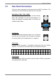
DVR User’s Manual 2.3 Rear Panel Connections There are various connectors on the rear panel for the DVR installations. The following shows the detailed description of each connector. Main Monitor (BNC / VGA / HDMI) The DVR supports three different types of main monitor: BNC, VGA, and HDMI. The main monitor displays Live image and playback recorded videos in full-screen or multiple-window mode. Call Monitor The BNC call monitor connector allows users to connect the DVR with a call monitor.
DVR User’s Manual Audio In/Out (16CH Models Only) 16CH models provide audio in/out connection via a D-Sub connector. Users can connect audio source devices for each channel and an audio output device for Main monitor. Refer to Setup Guide for detailed pin definitions for different models. Alarm I/O & RS-485 A D-Sub connector offers users the flexibility to connect the DVR to Alarm I/O and RS-485 devices. Refer to Setup Guide for detailed pin definitions for different models.
DVR User’s Manual 3. General System Setup Before operating the DVR, some general configuration should be setup first. The following subsections will introduce general configuration of the DVR. The regular displayed OSD information and its displayed position are shown as the following figure. The title of the channel is displayed on the top-center of the grid, either in full-screen mode or in multiple-window mode.
DVR User’s Manual 3.1.1 Functional Icons Move the cursor to the right side of the screen and a Live Panel will be displayed. This section describes the functional icons in the Live Panel. Please refer to Setup Guide for the graphical illustration of the functional icons. Enter/Zoom In Live and Playback full-screen mode, click on this icon to view a 2x zoom image. Click on this icon again to return to the Live or Playback full-screen mode. Esc Click on this icon to logout.
DVR User’s Manual Menu Click on this icon to enter the OSD setup menu. Dome Click on this icon to enter Dome Camera Control mode. Please refer to section Dome Control for detailed control operation. Channel In Live mode, click on any Channel icon to view the corresponding video in full-screen. NOTE: Users can also right click the mouse, and the pop-up list provides some similar functions, such as Mode List, Mode, Freeze, Search, Fast PB, Sequence, Menu, Call, and Dome. 3.
DVR User’s Manual 3.2.1 User Management The DVR provides the option to create up to seven sets of usernames and passwords with customized authority, excluding the preset “admin” account. From the OSD setup menu, select . The menu is as the following.
DVR User’s Manual Load Default Setting Select to load the default setting. 3.3 Power On / Shutdown / Reboot If the DVR must be rebooted or shutdown for any reason, please follow the proper shutdown procedures to avoid damaging the DVR. Power On the Unit After all required devices are connected, plug the power adaptor with the power supply cord in the DVR. Make sure the power source is between AC 110V to AC 240V. After the power key on the front panel is blinking, press it to power on the DVR.
DVR User’s Manual Auth: This will ask users to login with an authorized account, when Password Protection function is enabled. If Password Protection function is disabled, the action will be the same as the next option . Confirm: When this option is selected, a confirmation message will be shown after the Power Key is long pressed. Users can confirm or cancel the quick shutdown function.
DVR User’s Manual 3.3.1 HDD Auto Scan When the DVR is powering on, HDD auto scan will be initiated if there was previously an unusual power loss or file system error. If by any chance auto scan failed, the HDD will need to be formatted. NOTE: If users wish to disable the auto scan function, enter the OSD setup menu via an authorized account and access to set to . Read the following troubleshooting to finish the auto scanning process.
DVR User’s Manual 3.4 System Date / Time Setting Users can set the current date, time and other OSD parameters in Date/Time menu (under System menu). The login account should have authority to access the System menu. In the OSD setup menu, select , and then select to access the Date/Time menu; the menu displays as follows. Date/Time Date Time Time Zone Date/Time Display Date Display Mode Time Display Mode Daylight Saving Time Setup Network Time Protocol Setup 3.4.
DVR User’s Manual 3.4.2 Daylight Saving Time Daylight Saving Time The item is for people who live in certain regions to observe Daylight Saving Time. Select to enable, or to disable the function. If the function is disabled, the DST Start / End time and DST Bias will be grayed out and cannot be accessed. NOTE: If this function is enabled, the date / time information will be shown on the screen with a DST icon when playing back recorded video or searching video in the event list.
DVR User’s Manual NOTE: The
DVR User’s Manual 3.5.1 Record Mode Setup The Record Mode Setup menu allows users to setup record resolution, etc. The related record settings, such as preset configuration, will follow the record mode setting. The menu is displayed as the following. Record Mode Setup Record Resolution Record Format Max Rec. PPS CBR/VBR WD1 H264 480 CBR Select record resolution of the video from WD1, D1, and HD1. Record Format of the video is H.264. This item is “read-only”.
DVR User’s Manual 3.5.2 Schedule Setup The Schedule Setup is used to set the day and night time, or weekend recording schedule. Select from the Record menu; the following menu is displayed. Schedule Setup Day Time Start Day Time End Night Time Start Night Time End Weekend Schedule Weekend Start Weekend End AM 06:00 PM 06:00 PM 06:00 AM 06:00 On Fri PM 06:00 Mon AM 06:00 Make appropriate changes of the start time of Day and Night Time.
DVR User’s Manual 3.5.4 ezRecord Setup This item aims to ease the complicated record settings, and to make the setup much easier. Note that this item is only accessible when is selected as the option for . Select from , the sub-menu appears as below.
DVR User’s Manual 3.5.5 Advance Schedule Setup When is selected as the option for , users need to further configure the schedule and recording setting under this menu. The Advance Schedule setup menu is shown as below. Advance Schedule Setup Schedule Table Recording Profile Setup Holiday Setup NOTE: The menu can only be accessed when is set to . 3.5.5.
DVR User’s Manual 3.5.5.2 Recording Profile Setup Enter this menu to setup normal and event recording options for Profile 1, Profile 2 and Profile 3 for each channel. Follow the steps below to complete the setting. Recording Profile Setup Cameral Select Normal PPS Normal Qlty Normal Resolution Event Max PPS Event Qlty Copy Settings Profile 1 30 Best D1 30 Best Profile 2 30 Best D1 30 Best CH01 Profile 3 30 Best D1 30 Best Setup PPS (Picture per Second), quality and resolution for normal videos.
DVR User’s Manual 3.5.6 Data Lifetime Setup Data Lifetime indicates the duration that a video is saved and recallable in the HDD. Only those video recorded within Data Lifetime can be searched for playback. The video exceeds Data Lifetime will be hidden and cannot be retrieved for playback.
DVR User’s Manual 3.5.7 Circular Recording Users can choose to record video in circular mode or in linear mode. If circular mode is selected, the DVR will store new videos into the HDD spaces while overwriting the oldest recorded videos. Alternatively, if linear mode is selected, the DVR will stop recording when the HDD is full. The percentage of HDD usage will be displayed as an icon in the status bar. Moreover, an alert icon will be displayed in the status bar when HDD usage reaches 98%.
DVR User’s Manual Start To Purge After the video or data to be deleted are selected, set this item to to start the deletion or choose to cancel. 3.6 Event Setting This menu allows users to determine the behaviors of the DVR in response to alarm events. In the OSD setup menu, select , and the following menu is displayed. Items in the Event menu are described in the following subsections.
DVR User’s Manual 3.6.3 Alert Notification Setup This function allows users to send alert notifications to the CMS software which had been installed to users’ computer. For further setup instruction at the CMS side, please refer to the CMS user’s manual. Alert Notification Setup Alert Configuration Set Alert Notification Alert IP Alert Port Alive Interval 3.6.3.1 1 OFF 0.0.0.
DVR User’s Manual 3.6.4 Event Full Screen This function allows the DVR to display the alarm channel in full-screen size when an alarm is triggered. Select to disable this function; select to display the alarm channel on Main Monitor when an alarm is triggered; select to display the alarm channel on Call Monitor; and select to display the alarm channel on both Main Monitor and Call Monitor. 3.6.
DVR User’s Manual 3.6.6.3 Motion Detect This item allows users to enable / disable motion detection function of the DVR. Select to enable Motion Detect alarm events, or to disable. If motion detection function is enabled, it is required to define motion detection parameters, such as detection area and sensitivity settings in . 3.6.6.4 Detection Configuration If motion detection function is enabled, the motion detection parameters should be setup.
DVR User’s Manual Area Threshold indicates the motion trigger level. If the percentage of the triggered grids from the total detection area is greater than the set value, the motion alarm will be triggered. For example, if 10 girds are selected and the value is 70%, the motion alarm will be triggered when 7 grids are motion-detected. Adjust the percentage by clicking UP / DOWN buttons next to . The value is increased by 1% increment. 3.6.6.
DVR User’s Manual 3.6.7 E-mail Management Users can setup three sets of e-mails for receiving event/alarm notices. Follow the brief steps below to setup the e-mail management setting. NOTE: In order to successfully send a notification e-mail, be sure that the DVR is connecting to the internet.
DVR User’s Manual 4. Basic Operation This chapter will introduce the general operations of the DVR. 4.1 View Live / Playback Video The general functions in Live and Playback mode are described in the following sections. 4.1.1 Viewing Modes The DVR provides users several display modes. Click on any CHANNEL directly to view the corresponding camera in full-screen mode. In addition, click on the Mode icon in the Live Panel to view in multiple-window mode.
DVR User’s Manual 4.1.3 Camera Info When users move the cursor to the camera title at the top center of each channel, the camera information will be displayed. The information includes the type of camera, FPS, quality, resolution, and video format of the camera. 4.1.4 View Live Cameras Users are allowed to view live camera in versatile viewing modes, including full-screen, 4-window, 9-window, and 16-window. The general operation under Live mode is described as follows.
DVR User’s Manual Playback Control Panel The Playback Control Panel will be displayed during the playback. Refer to the following description for each control item. 36 Time Bar: The time bar will show available normal videos in yellow, while the event videos will be displayed in red. Users can directly click on the time bar to select the preferred playback time. Previous Time Step: Click on this icon to change the displayed time bar to the previous time frame.
DVR User’s Manual 12hr: Click on this icon to scale the time bar by 12 hours. 4hr: Click on this icon to scale the time bar by 4 hours. NOTE: Users can also click and drag the time slider bar to select a preferred playback video time. For more information about the Search menu and quick video export, please refer to sections Search Recorded Video and Quick Video Export. Key Usage of Remote Controller Refer to the following for key usage of the remote controller in Playback mode.
DVR User’s Manual 4.1.6 Capture Snapshots When the Playback video of a single channel display is paused, users can click on the Enter icon in the Live Panel to capture and export snapshots to an external storage device, excluding optical drives. Note that the system log will keep a record of any snapshot exportation. 4.2 Sequence This section introduces how to view Sequence mode with both Main Monitor and Call Monitor, if connected.
DVR User’s Manual 4.3 Search Recorded Video The DVR is capable of searching and playing back the recorded videos by date / time or events. To search by time, select a specific date and time of the wanted video. To search by event, select the event type and channels to display the event list. In Live or Playback mode, click on the Search icon in the Live Panel to enter the Search menu, shown as below.
DVR User’s Manual 4.3.2 Calendar Search Follow the steps below to search recorded video via Calendar Search. Select , and the following menu will be displayed. Select any date shown in underlined font, which indicates the recording data are available. The table shown on the left will display available videos of each channel within the selected date. The videos are classified into four categories: Normal, Motion, Alarm In and Video Loss, shown as four different tabs on the top.
DVR User’s Manual 4.3.3 Search by Event Follow the steps below to search event video through Event List. Adjust date / time next to and under to specify time range of the event search. Next to
DVR User’s Manual 4.4 Video Export The following sections will show how to export video through the OSD setup menu and via the quick export function. Note that the system log will keep records of all video exportations, including duration, start time, and end time. NOTE: Make sure an external storage device is available and connected to the appropriate port for video export. NOTE: The exported videos will be in Main stream. 4.4.
DVR User’s Manual 4.4.1.1 Select the External Device The available external devices for exporting video will be listed by name and free size in the Select Device menu, which is displayed as follows. Select Device Device Name xxx-xxx-x-x-xx xx-xxx-xx-xxxx Available 256 MB 1.5 GB Sel No No NOTE: The DVR only exports files to external USB drives with FAT32 format.
DVR User’s Manual From / To Time The items are used to set the time which data export begins and ends. Click to choose date / time and scroll the mouse wheel to adjust the values. Select Events Click on this item to display the event list. Set column of the exporting event(s) to . NOTE: This is only available when is set to or . Data Type The item is used to select exporting video type.
DVR User’s Manual 4.4.1.4 Begin Export Set this item to and the DVR will prepare to export the select recorded video. The Backup Confirmation window will be displayed for users to double confirm data of the exporting video. Click to begin the exportation. 4.4.2 Quick Video Export In the Playback Control Panel, the Copy icon allows users to easily export the wanted video as *.drv file to an external device, such as a USB ThumbDrive.
DVR User’s Manual 4.4.3 Export Normal Video To export normal video to external devices, follow these steps: Click on the Search icon in the Live Panel, and playback the preferred normal video. Refer to section Search by Time or Calendar Search for information about normal video playback. In Playback mode, the Playback Control Panel will be displayed. Click on the Copy icon once to mark the starting point of the export video. The playback continues.
DVR User’s Manual 4.4.4 Export Event Video To export event video, follow these steps: Click on the Search icon in the Live Panel, and playback the preferred event video. Refer to section Searching by Event for information about event playback. In Playback mode, click on the Copy icon. The confirmation message will be displayed as the figure below. The shown information is “read-only”.
DVR User’s Manual 4.5.2 Dome Protocol Setup The Dome Protocol item lists the available dome protocols for communicating with dome cameras connected to the DVR. From the OSD setup menu, select and the following menu is displayed. Camera Analog Camera Select Dome Protocol Dome ID Camera Name Covert Termination Adjust Video Audio Association Copy Setting CH01 None 0 CH1 No Yes Yes To configure dome protocol, select a camera first and set the communications protocol associated with dome camera.
DVR User’s Manual NOTE: The changed settings take effect after users exit the setup menu. 4.5.4 Dome Control Buttons After the DVR is in Dome Control mode, a Dome Control Panel will be displayed. The control buttons are: Iris Close/Open, Focus Far/Near, Zoom Out/In, Preset, Live, Pan/Tilt Speed, Direction buttons, and Auto Focus. The functions are described as below. NOTE: There will be no reaction when users click on the control functions that are not supported by the dome cameras.
DVR User’s Manual Pan/Tilt Speed Users can select preferred pan/tilt speed. Direction Buttons Click on the buttons to pan and tilt the lens of selected dome camera. Auto Focus Click on this button to automatically adjust focus of the dome camera. 4.5.5 Set Preset Points The DVR allows users to set preset positions. The amount of preset points depends on the dome manufacturer. Follow the steps to set preset points. Click on a dome camera channel to display it in full-screen.
DVR User’s Manual Click on the Preset button on the Dome Control Panel to access the Set/Go Preset function. A numeral keyboard will be displayed. Input a desired preset number. Click on the button to call the preset point. Then, the selected dome camera will rotate to the preset position automatically. 4.5.7 Run Dome Camera Tour Users can also display dome camera tour setup at the dome camera side. Follow the steps to run display of dome camera tour.
DVR User’s Manual 5. Remote Monitoring Software The remote monitoring software is a remote browser-based software designed to operate with the DVR products. By using the software, users are allowed to view live and recorded video, and configure the DVRs remotely via a LAN, WAN or Internet on a personal computer. The connected PC will automatically download the remote monitoring software plug-ins from the DVR when the DVR is connected by entering its IP address in the address bar of the browser.
DVR User’s Manual 5.2 Software Installation Before operating the remote monitoring software, please first find out the IP address of the DVR. To find the IP address, enter the OSD setup menu and select . Refer to the following description to install the remote monitoring software. 5.2.1 Change Internet Settings The PC operating with the remote monitoring software should be set to accept ActiveX plug-ins.
DVR User’s Manual Uncheck “Require server verification (https:) for all sites in this zone”. Type the IP address of the unit in field and click to add this web site to the zone. Click to confirm the setting and close Trusted sites dialog. In the Security Level area, click . The Security Settings screen is displayed. Under , set all items to or . Click to apply the setting and close the screen.
DVR User’s Manual 5.2.2 Install the Remote Monitoring Software With the IP address of the DVR, the next step is to install the remote monitoring software via connecting to the DVR. Follow the steps below. Enter the IP address of the DVR in the address bar of the web browser. The IP address of the DVR can be saved as a Favorites item in the web browser to enable easy access in the future. The ActiveX controls and plug-ins dialog will show twice for confirmation.
DVR User’s Manual 5.2.2.1 Login / Logout Login with the same accounts setup in the DVR. The authority level of the accounts is also the same as what was setup in the DVR. One preset account “admin” and up to two other accounts can access a DVR at the same time. However, if the “admin” account is currently accessing the OSD setup menu of the DVR at the DVR side, then the “admin” account at the remote monitoring site cannot change the settings at the same time.
DVR User’s Manual 5.2.2.2 Software Upgrades If a new version of the remote monitoring software is available on the DVR, upgrade will be prompted while accessing the unit. Follow the steps to upgrade the software. The message as the above figure will be prompted. Click to accept version upgrade. Start the IE again and enter the IP address of the DVR in the address bar of the browser; or if the unit address is set as a Favorite site, click the Favorites entry for the unit.
DVR User’s Manual 5.3.1.1 Select Display Mode Choose the number of windows to be displayed on the main window. Click one of the display buttons in MODE section. Available selections are 4, 9 and 16 camera displays. To view certain window in full-screen, either double-click on the wanted window, or click on the corresponding CAMERA button. 5.3.1.2 Operate Cameras with Dome Control The remote monitoring software allows users to control and configure a dome camera remotely.
DVR User’s Manual Iris +/− This item is used to open and close the iris to let more or less light into the camera. Click on to open iris or to close iris. Zoom +/− Users are allowed to zoom-in or zoom-out by using the adjusting buttons. Zoom-in to enlarge a certain area and zoom-out to view more area. Direction Button This button is used to pan and/or tilt the dome camera. Click the arrows in the directions to be viewed. 5.3.1.
DVR User’s Manual 5.3.2 Instant Recording The Instant Recording function allows users to record video quickly to the PC. NOTE: The Audio function is set to OFF by default. 5.3.2.1 Record Video Instantly Follow the steps to start recording instantly: Click on the button. Select the destination folder to save the video. Click on the button again to stop recording. NOTE: The instant recording video will be saved as *.drv file. 5.3.2.
DVR User’s Manual 5.3.3.1 Playback Remote Video To view remote video, click on the main window toolbar, and then tab. The screen will be displayed. The and in the display the date and time from which recorded video is available for playback. The calendar on the right indicates dates with available videos. The time slider bar is shown for different channels with classified event videos.
DVR User’s Manual 5.3.3.2 Playback Local *.drv Files The tab allows users to playback *.drv video files stored in the PC's hard drive. Follow below steps to playback a downloaded *.drv file with the remote monitoring software. Click and the file selection screen is displayed. Select the *.drv video file for playback and click . Click in the Screen to start the playback, or click to abort.
DVR User’s Manual 5.3.4 Verify Digital Signature The digital signature aims to authenticate a video file exported from the unit. Follow the description to verify the digital signature. Click on the main window toolbar. Click tab to display the Verify window. Click to select the *.gpg, *.avi, *.sig files respectively, which belong to the exported video to be authenticated. Click to start verifying digital signature.
DVR User’s Manual 5.3.6 Take a Snapshot Snapshot is a simple screen capture tool. When users click on the SNAPSHOT button, it will capture the screenshot of the window that is currently showing on the screen. Each click captures one screenshot to be saved as a JPEG file on the desktop. The snapshot file will be named as “Snapshot-*”. NOTE: To ensure that the snapshot files can be saved on the desktop, users must run IE as administrator.
DVR User’s Manual 5.3.8 Normal and Dual Streaming For different networks with different bandwidths, two streaming options are provided – normal and dual streaming. The preset is normal streaming. Users who are using high-speed networks, normal streaming will be a recommended choice. According to the HDD capacity and network usage, set the remote monitoring software to occupy high or low bandwidths. For networks with limited bandwidth, dual streaming will be a better choice.
DVR User’s Manual Remotely Reboot Also from the Configuration window, access the Shutdown menu as shown below. Then click on the Execute button to remotely reboot the DVR. 5.3.10 Remote Monitoring Software Troubleshooting What happened if the server requests to upgrade the software every time the DVR is connected? If the following screen displays repeatedly, please follow the steps to delete the temporary internet files.
DVR User’s Manual Click the button in the field; the window displays as below. Check the box and click . Now, enter the IP address of the DVR to make the connection again.
DVR User’s Manual Appendix A: Keyboard Access Sketch The following sketch shows the keys used to access and control the connected DVR.
DVR User’s Manual Appendix B: Remote Controller The operational function keys on the remote control are listed as below figure: 69
DVR User’s Manual The keys of the remote control function as the icons of the Live Panel of the DVR. The only difference between the two is the “DVR SEL” key. The DVR Selection key is used to switch control between each DVR. The remote control can be used to control up to 16 DVRs. To setup the remote control, the first thing is to assign a unique DVR Unit ID to each DVR. Use the Live Panel of the DVR, and follow this path to change the DVR Unit ID, .
DVR User’s Manual Appendix C: Setup a DVR Behind a Router This appendix describes how to set up a router if the DVR connects to the internet via a router. To properly operate a web server, e.g. a DVR, users have to set up both the IP and port of the DVR, which are essential for data and command transmission. The port setting is adjustable in OSD setup menu of the DVR and only one port is needed to do remote operation.
DVR User’s Manual Following is an example of how the router should be set. Router (D-Link DI-724P+) WAN IP: 218.160.54.13 LAN IP: 192.168.0.1 PC IP: 192.168.0.100 DVR 1 IP: 192.168.0.167 Trigger port: 80 DVR 2 IP: 192.168.0.200 Trigger port: 81 To change the setting of the router, a PC with web browser is required. Connect to D-Link DI-724P+ from PC via IE. The setup screen will be shown after entering the correct username and password.
DVR User’s Manual A. Select to set up the service. B. Enter the name of the setting in the Name field: DVR 1. C. Enter Private IP: 167 D. Choose as the Protocol Type. E. Enter Private Port: 80. F. Enter Public Port: 80. G. Click for the Schedule setting. H. Click . Click to go on when the following screen displays. Follow the steps to set up web port forward to DVR 2. A. Click to set up the service. B.