
Use and Care Manual

13
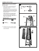
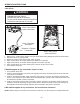
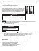
13. Note: Do not cover the front side where
the control knob is located.
Attach the two side panels (L) to the
lower supports (K) using eight M5 x 12
mm screws (EE). Tighten with the Phillips
screwdriver (OO).
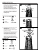
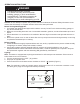
14. Install the knob (KK) and the chain and
long stem lighter assembly (MM) using one
M4 x 6 screw (LL) as illustrated in gure
14A.
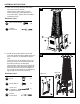
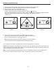
Insert the hooks at the bottom of the front
panel (S) into the corresponding holes at
the bottom plate (R) as illustrated.
Take the hook at the other end of the chain
and long stem lighter assembly (MM) and
attach it to the hole next to the magnet on
the control box assembly (I) as illustrated in
gure 14B. Close the front panel (S).
ASSEMBLY INSTRUCTIONS
Hardware Used
Hardware Used
13
14
Phillips
screwdriver
Phillips
screwdriver
Chain and
Long Stem
Lighter Assembly
M5 x 12 mm Screw
Knob
Screw M4 x 6
x 8
x 1
x 1
x 1
EE
KK
LL
OO
OO
MM
EE
L
S
MM
LL
KK
K
Figure 14A
Figure 14B
I
R