
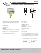
Install Instructions

©Copyright 2014 Dwyer Instruments, Inc. Printed in U.S.A. 9/14 FR# R5-443380-00 Rev. 1
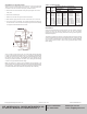
Once you have the correct vane length, you can then adjust the flow rate setting
by means of the adjustable bolt shown in Figure 2. Fully tighten the adjustable bolt
to obtain the minimum flow rate setting. Fully loosen the adjustable bolt to obtain
the maximum flow rate setting. The adjustable bolt can be adjusted and set
according to practical requirements. See Table 1 for the limiting flow rate settings
in relation to the pipe diameter and blade length.
Note: The Model FS-2 is shipped with the adjustable bolt fully tightened, in the
minimum setting. Also, the pre-set bolt shown in Figure 2 has been adjusted before
leaving the factory. Users should not adjust this by themselves. Adjustment of the
pre-set bolt could lead to switch malfunction and possibly void the warranty.
Figure 2: Adjustment
M
AINTENANCE
I
nspect and clean wetted parts at regular intervals. The cover should be in place at
a
ll times to protect the internal components from dirt, dust, and weather.
Disconnect the device from the supply circuit before opening to prevent ignition of
hazardous atmosphere.
The Model FS-2 Paddle Flow Switch is not field serviceable and should be returned
i
f repair is needed (field repair should not be attempted and may void warranty). Be
s
ure to include a brief description of the problem plus any relevant application
notes. Contact customer service to receive a return goods authorization number
b
efore shipping.
A
DJUSTMENT OF FLOW RATE SETTING
Determine the correct blade length, which is based on the size of your pipe (see
T
able 1). Remove only those layers which are too long. Leave the smaller layers
o
n to reinforce the vane. To remove vane layers, proceed as follows:
a. Remove the screw and lockwasher holding the layers together. Do not lose
these parts.
b
. Remove the unwanted layers.
c. Resecure the vane with the original screw and lockwasher.
d. With a hammer, lightly peen the end of the screw so that it can not back out.
e. If you lose the screw or lockwasher, do not replace with other parts which may
c
orrode and break. That will void the warranty and might cause severe damage
to equipment located downstream of the switch.
P
ipe
Diameter
(inch)
1
1
-1/4
1
-1/2
2
2
-1/2
3
4
5
6
8
B
lade
L
ength
i
n (mm)
Dim. X
1.34 (34)
1.34 (34)
2
.24 (57)
2
.24 (57)
3
.46 (88)
3
.46 (88)
3.46 (88)
6.57 (167)
6.57 (167)
6
.57 (167)
A
pproximate Actuation and Deactuation
F
low Rates for Water
M
inimum Setting
G
PM (LPM)
M
aximum Setting
G
PM (LPM)
A
ctuate
4
.0 (15.0)
5
.3 (20.0)
7
.0 (26.7)
14.1 (53.3)
18.5 (70.0)
27.7 (105.0)
5
9.4 (225.0)
5
2.8 (200.0)
7
5.7 (286.7)
1
84.9 (700.0)
Actuate
8.8 (33.3)
11.4 (43.3)
1
4.5 (55.0)
3
1.3 (118.3)
3
5.2 (133.3)
5
2.8 (200.0)
123.3 (466.7)
132.1 (500.0)
154.1 (583.3)
3
96.3 (1500.0)
D
eactuate
1
.8 (6.7)
2
.6 (10.0)
4.0 (15.0)
9.7 (36.7)
15.4 (58.3)
2
5.1 (95.0)
5
2.8 (200.0)
3
9.6 (150.0)
5
2.8 (200.0)
158.5 (600.0)
D
eactuate
6
.6 (25.0)
8.4 (31.7)
11.4 (43.3)
22.5 (85.0)
3
0.8 (116.7)
4
6.2 (175.0)
1
14.5 (433.3)
1
23.3 (466.7)
140.9 (533.3)
374.2 (1416.7)
T
ABLE 1: FLOW RATE CHART
Phone: 219/879-8000 www.dwyer-inst.com
Fax: 219/872-9057 e-mail: info@dwyermail.com
W.E. ANDERSON DIV., DWYER INSTRUMENTS, INC.
P.O. BOX 358 • MICHIGAN CITY, INDIANA 46360 U. S.A.