
Install Instructions

©Copyright 2020 Dwyer Instruments, Inc. Printed in U.S.A. 10/20 FR# 443277-10 Rev. 8
Wire Length – The maximum length of wire connecting transmitter and receiver is
a function of wire size and receiver resistance. Wiring should not contribute to more
than 10% of receiver resistance to total loop resistance. For extremely long runs (over
1000 ft or 305 m), choose receivers with higher resistance to minimize size and cost
of connecting leads. When wiring length is under 100 ft (30.5 m), lead wire as small
as 22 AWG can be used.
Current (4-20 mA) Output Operation – An external power supply delivering 10-35
VDC with minimum current capability of 40 mA DC (per transmitter) is required to
power the control loop. See Figure 9 for connection of the power supply, transmitter,
and receiver. The range of the appropriate receiver load resistance (RL) for the DC
power supply voltage available is expressed by the formula
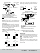
VOLTAGE (0-5, 1-5, 0-10, OR 2-10 V) OUTPUT OPERATION
To select the voltage output that is going to be used, congure the dip switches
according to the Figure 8 below. Power must be cycled whenever dip switches are
changed to select output.
0-5 VDC
1 2
1 2
1 2
1 2
ON
OFF
ON
OFF
ON
OFF
ON
OFF
1-5 VDC
0-10 VDC 2-10 VDC
PRESSURE
TRANSMITTER
1
RECEIVER
2
3
4
SHIELD
COM
VIN
+-
+
-
VO
POWER
SUPPLY
13-35 VDC
OR 16-33 VAC
TRANSMITTER CONNECTION INSTRUCTION:
-
TURN OFF POWER SUPPLY.
- CONNECT
THE POWER SUPPLY [+] TO Vin [TERM #1] AND [-] TO Com [TERM #2] OF
THE GAGE AS SHOWN.
- CONNECT
THE RECEIVER [+] TO Vo [TERM #3] OF THE GAGE AND RECEIVER [-] TO
POWER SUPPL
Y [-].
- INST
ALL THE LCD'S CONNECTOR TO THE GAGE AS SHOWN.
- SET
VOLTAGE SELECTION DIP SWITCH TO DESIRED VOLTAGE OUTPUT.
-
TURN ON POWER.
CAUTION: BE SURE
TO TURN OFF POWER WHEN CONNECTING OR REMOVING THE
LCD CONNECTOR. FAILURE TO DO SO CAN RESULT IN GAGE DAMAGE.
WHITE
YELLOW
ORANGE
BLUE
BLACK
RED
SHILED [TERM #4]
Com [TERM #2]
Vin [TERM #1]
-
+
RECEIVER
-
+
LCD CONNECTOR
HI [+]
PRESSURE
CONNECTIO
N
LOW [-]
PRESSURE
CONNECTION
UNIT BUTTON-PRESS TO TOGGLE THE
UNIT [PSID/BARD] ON THE LCD
ZERO BUTTON-PRESS AND
HOLD TO ZERO THE GAG
VOLTAGE SELECTION
DIP SWITCH
Vo [TERM #3]
POWER
SUPPLY
13-35 VDC
OR ISOLA
TED
16-33 VAC
For voltage outputs, wire as shown in Figure 9 for voltage output connection. Use
Figure 10 for voltage output with optional LCD display. Terminal 1 is positive (+),
terminal 2 is negative (-), and terminal 3 is +Vout. If ordering optional prewired cable,
black wire is negative (-), red wire is positive (+), and white wire is +Vout. For optimal
accuracy, use a separate common wire for the receiver.
MAINTENANCE/REPAIR
Upon nal installation of the Series 629C Wet/Wet Differential Pressure Transmitter,
no routine maintenance is required. The Series 629C is not eld serviceable and is not
possible to repair the unit. Field repair should not be attempted and may void warranty.
WARRANTY/RETURN
Refer to “Terms and Conditions of Sale” in our catalog and on our website. Contact
customer service to receive a Return Material Authorization number before shipping
the product back for repair. Be sure to include a brief description of the problem plus
any additional application notes.
Atur alicit faccae volorerent faccae modiam veribus dendis maio. Itatur?
Ipsant plaut dolores eius.
Olum utem. Ut porepel idi oditias periossint faccusd aecatius quam ario denimagnis
Figure 8: Voltage output dip switch selection
Figure 9: Voltage output connection
Figure 10: Voltage output with optional LCD display
WHITE
YELLOW
ORANGE
BLUE
BLACK
RED
SHIELD [TERM #4]
Com [TERM #2]
Vin [TERM #1]
POWER
SUPPLY
10-35 VDC
-
+
RECEIVER
-
+
LCD CONNECTOR
HI [+]
PRESSURE
CONNECTION
LOW [-]
PRESSURE
CONNECTION
UNIT BUTTON-PRESS TO TOGGLE THE
UNIT [PSID/BARD] ON THE LCD
ZERO BUTTON- PRESS AND
HOLD TO ZERO THE GAGE
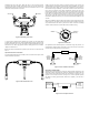
TRANSMITTER CONNECTION INSTRUCTION:
-
TURN OFF POWER SUPPLY.
- CONNECT
THE POWER SUPPLY AND RECEIEVER TO Vin [TERM #1] AND Com
[TERM #2] OF
THE GAGE AS SHOWN.
- INST
ALL THE LCD'S CONNECTOR TO THE GAGE AS SHOWN.
-
TURN ON POWER.
CAUTION: BE SURE
TO TURN OFF POWER WHEN CONNECTING OR REMOVING
THE LCD CONNECTOR. FAILURE TO DO SO CAN RESULT IN GAGE DAMAGE.
Figure 7: Current output with optional LCD
RL max =
vps - 10
20 mA DC
This symbol indicates waste electrical products should not be disposed
of with household waste. Please recycle where facilities exist. Check with
your Local Authority or retailer for recycling advice.
DWYER INSTRUMENTS, INC.
P.O. BOX 373 • MICHIGAN CITY, INDIANA 46360, U.S.A.
Phone: 219-879-8000
Fax: 219-872-9057
www.dwyer-inst.com
e-mail: info@dwyermail.com