
Install Instructions
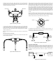

Installation with 3-way valve option. Begin with valve V1 open and valves V2 and
V3 closed. (See Figure 2) Slowly open valves V2 and V3. Once the pressure has
stabilized and is equal on the high and low side of the transmitter, valve V1 can be
closed and normal operation can proceed.
To ensure proper pressures will be detected by the 629C, use the bleed ttings
provided with this package to free media of bubbles. Before applying pressure to the
process connections, turn V1 to the open position and back off either the low or high
side bleed hex nut. Next, apply pressure. After the owing liquid is free of bubbles,
retighten the bleed hex nut.
Before removing the transmitter from operation, open valve V1, then close valves V2
and V3.
Optional Remote Sensor Installation
For both shielded cable and armored cable versions of remote sensors option, follow
standard installation procedures.
Install the high and low remote sensors in respective locations in the process. Use
of thread sealant is recommended to prevent leaks. During installation, care must be
taken to ensure that the serial number on the sensor matches the serial number on
the transmitter housing. Additionally, a check must be made to ensure that the check
box for high or low pressure on the sensor matches the check box for high or low
pressure on the cable tag. The sensor with a mark in the “High Pressure” box should
be connected to the higher pressure, and the sensor with a mark in the “Low Pressure”
box should be connected to the lower pressure in order to ensure accurate readings.
The vent hole on the side of the unit should not be covered by anything aside from
the ber lter installed from the factory. Do not remove the ber lter installed over the
vent hole.
After sensor installation, attach the cable to the sensor by means of the M-12 connector
shown in Figure 4. The cables connecting the sensors to the transmitter housing can
only be disconnected at the sensor by means of the M-12 connectors. No attempt
should be made to disconnect remote cables at the transmitter housing.
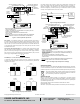
For applications where differential pressure is measured at high line pressure, it is
recommended to install pressure sensor with a valve in each line and a shunt valve
across the high and low pressure ports (see Figure 5).
ELECTRICAL CONNECTIONS
Shielded cable is recommended for control loop wiring. Electrical connections to the
Series 629C pressure transmitters are made to the terminal block located inside the
housing. Remove the screws and lift off the cover. Wire as shown in Figure 6 or 7. Use
Figure 6 for current output connection. Use Figure 7 for current output with optional
LCD display. If ordering pre-wired cable, black wire is negative (-) and red wire is
positive (+).
PRESSURE
TRANSMITTER
1
RECEIVER
2
3
4
SHIELD
COM
VIN
+-
+
-
POWER
SUPPLY
10-35 VDC
Figure 2: Bleed tting connections
Figure 4: M-12 connector
Figure 5: Sensor installation with valves
Figure 6: Current output connection
BLEED FITTING
HIGH SIDE
BLEED FITTING
LOW SIDE
HIGH
PRESSURE
REMOTE
SENSOR
SHUNT
VALVE
629C-RS
LOW
PRESSURE
REMOTE
SENSOR
PIPE
SHUNT
VALVE
TERMINAL 4: [-]
TERMINAL
1: [+]
TERMINAL
3:
[GROUND]
Figure 3: 629C with remote sensor
NEVER PUT STRESS ON HOUSING.
ALWAYS USE WRENCH ON PRESSURE BLOCK
WHEN TIGHTENING FITTING.
CAUTION: