
Install Instructions
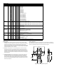

MODEL CHART
Example 629C -01 -CH -P1 -E1 -S1 -3V 629C-01-CH-P1-E1-S1-3V
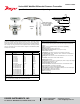
Series 629C Wet/wet differential pressure transmitter
Range 01
02
03
04
05
06
07
08
09
11
12
13
14
15
16
17
18
19
0 to 5 psid
0 to 10 psid
0 to 25 psid
0 to 50 psid
0 to 100 psid
0 to 150 psid
0 to 200 psid
0 to 300 psid
0 to 500 psid
0 to 0.5 bar differential
0 to 1 bar differential
0 to 2 bar differential
0 to 4 bar differential
0 to 6 bar differential
0 to 10 bar differential
0 to 15 bar differential
0 to 20 bar differential
0 to 30 bar differential
Housing CH
R1
R2
R5
R6
Conduit housing, NEMA 4X (IP66)
Conduit housing, NEMA 4X (IP66), with remote sensor and 10´ shielded cable
Conduit housing, NEMA 4X (IP66), with remote sensor and 20´ shielded cable
Conduit housing, NEMA 4X (IP66), with remote sensor and 10´ armored cable
Conduit housing, NEMA 4X (IP66), with remote sensor and 20´ armored cable
Process
Connection
P1
P2
P3
P4
1/4˝ male NPT
1/4˝ female NPT
1/4˝ male BSPT
1/4˝ female BSPT
Electrical
Connection
E1
E2
E3
E5
E9
Cable gland with 3´ of prewired cable
Cable gland with 6´ of prewired cable
Cable gland with 9´ of prewired cable
1/2˝ female NPT conduit
M-12 4 pin connector (not UL)
Signal Output S1
S3
4-20 mA
Field selectable 0-5, 1-5, 0-10, 2-10 VDC
Options 3V
AT
FC
LCD
NIST
3-way valve
Aluminum tag
Factory calibration certicate
LCD indication
NIST traceable certicate
*Pressures exceeding the working pressure limit may cause a calibration shift of up to ±3% of full-scale.
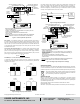
INSTALLATION
1. Location: Select a location where the temperature of the unit will be between
0 and 200°F (-18 to 93°C). Distance from the receiver is limited only by total loop
resistance (see electrical connections). The tubing feeding pressure to the \
instrument can be practically any length required, but long lengths will increase the
response time slightly. Mount the instrument in a location that will not be subject to
excessive temperature, shock, or vibration.
2. Position: A vertical position is recommended (pressure connections pointing
horizontally) since that is how all standard models are spanned and zeroed at
the factory. They can be used at other angles, but may require nal zeroing. Due
to potential condensation buildup that may travel down conduit or cable and into
the housing, it is recommended to install with the electrical conduit or cable gland
pointing downward.
3. Pressure Connection: Dual 1/4˝ NPT pressure connections are provided. Use
pipe thread sealant tape or other suitable pipe joint compound when making
connection to the pressure source. Avoid excess sealant which could block the
pressure passage. When monitoring liquid pressures, air trapped in the lines can
cause incorrect readings. Bleed ttings or similar mechanisms should be used to
bleed off any trapped air.
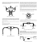
Optional 3-Way Valve
For applications where higher line pressures may be encountered at installation or
when it is necessary to remove the transmitter for maintenance without interrupting the
process, the optional three way valve is recommended. (See Figure 1)
7-17/64 [184.66]
2-13/32
[60.96]
3-63/64
[101.02]
5-19/32
[142.11]
4-17/64
[108.33]
2-25/64
[60.84]
3 [76.19]
1-37/64
[40.14]
Figure 1: 629C with optional 3-way valve