Bulletin E-90-CPC Series 4C, 8C and 16C Microprocessor Based Temperature Process Control Specifications - Installation and Operating Instructions LOVE CONTROLS DIVISION DWYER INSTRUMENTS INC. P.O. BOX 338 - MICHIGAN CITY, INDIANA 46360, U.S.A. Phone: 219/879-8000 www.love-controls.com Fax: 219/872-9057 e-mail:love@love-controls.
TABLE OF CONTENTS Model Number Identification . . . . . . . . . . . . . . . . . . . . . . . . . . . . . 3 Getting Started . . . . . . . . . . . . . . . . . . . . . . . . . . . . . . . . . . . . . . . . 3 Installation . . . . . . . . . . . . . . . . . . . . . . . . . . . . . . . . . . . . . . . . . . . 4 Panel Cutout Dimensions . . . . . . . . . . . . . . . . . . . . . . . . . . . . . . . 4 Mounting . . . . . . . . . . . . . . . . . . . . . . . . . . . . . . . . . . . . . . . . . . . . 5 Wiring Diagrams . .
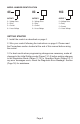
MODEL NUMBER IDENTIFICATION 4C 8C 16C OUTPUT 1 2 = Voltage Pulse 3 = Relay 5 = Current 6 = Linear Voltage OUTPUT 1 2 = Voltage Pulse 3 = Relay 5 = Current 6 = Linear Voltage OUTPUT 1 2 = Voltage Pulse 3 = Relay 5 = Current 6 = Linear Voltage GETTING STARTED 1. Install the control as described on page 4. 2. Wire your control following the instructions on page 6. Please read the Precautions section located at the end of this manual before wiring the control. 3.
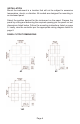
INSTALLATION Mount the instrument in a location that will not be subject to excessive temperature, shock, or vibration. All models are designed for mounting in an enclosed panel. Select the position desired for the instrument on the panel. Prepare the panel by cutting and deburring the required opening per the panel cut out dimensions listed below. Follow the mounting instructions listed on page 5. Lastly, wire the controller per the appropriate wiring diagram listed on page 6.
MOUNTING METHOD Step 1: From the front of the panel, slide the controller housing through the cut out. The housing gasket should be against the housing flange before installing. Step 2: Insert the mounting brackets into the mounting grooves on the top and bottom of the controller (4C, 8C, and 16C). Step 3: Push the mounting brackets forward until the bracket stops at the panel wall. Step 4: Insert and tighten the screws on the bracket to secure the controller in place. (The screw torque should be 0.
WIRING Do not run thermocouple or other class 2 wiring in the same conduit as power leads. Use only the type of thermocouple or RTD probe for which the control has been programmed. Maintain separation between wiring of sensor, auxiliary in or out, and other wiring. See the Initial Setting Menu for input selection. For thermocouple input always use extension leads of the same type designated for your thermocouple. For supply connections use No. 16 AWG or larger wires rated for at least 75˚ C.
FRONT KEY FUNCTIONS Key functions are as follows: INDEX: Pressing the INDEX key advances the display to the next menu item. UP ARROW: Increments a value or changes a menu item. If pressed during the Operation Mode, the set point value will be increased. DOWN ARROW: Decrements a value or changes a menu item. If pressed during the Operation Mode, the set point value will be decreased. ENTER: Stores the value or item change. If not pressed, the previously stored value or item will be retained.
CONTROL OPERATION DESCRIPTION The HOME display is the normal display while the control is operating. If no errors or functions are active, the HOME display will indicate the Process Variable that is being measured on the top display and the Set Variable on the bottom display. Error Messages are shown on page 18. Heating or Cooling Temperature Control can be achieved by either heating or cooling. Please refer to the following for the operation of each setting.
PROGRAMMING AND OPERATION FOR PID Theory of Operation The PID method of control is based on the individual tuning of proportional band values, integral time values, and derivative time values to help a unit automatically compensate for changes in a control system. The proportional band is the range around the set point in which the control’s proportioning takes place. The control increases or decreases the output proportionately to the process temperature’s deviation from the set point.
DESCRIPTION OF MENU STRUCTURE The programming for the controller is broken down into three menus (Operation, Regulation, and Initial Setting). Upon normal operation, control will be in the Operation Menu. OPERATION MENU Pressing the INDEX key will cycle through the below menu items. The parameter will be displayed in the top display, while its value will be displayed in the bottom display, except for the set point which is displayed in the bottom display on the Home Display.
REGULATION MENU Press the ENTER key while at the Home Display in order to access the Regulation Menu. Pressing the INDEX key will cycle through the below menu items. The parameter will be displayed in the top display, while its value will be displayed in the bottom display. The UP and DOWN arrows change the values of the parameters. The ENTER key must be pressed after any changes. AT Auto Tune. The controller will evaluate the process and select the PID values to maintain good control.
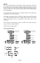
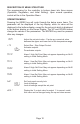
Figure A: Output behavior for Heating/Cooling On/Off Applications HtPd Heating Control Cycle Setting. Defines the duration for one output period or cycle for output 1. Only available when control mode is set to PID and Output 1 is set for heating. CLPd Cooling Control Cycle Setting. Defines the duration for one output period or cycle for output 1. Only available when control mode is set to PID and Output 1 is set for cooling. tPoF Process Temperature Offset.
INITIAL SETTING MENU Press and hold the ENTER key for at least 3 seconds while at the Home Display in order to access the Initial Setting Menu. Pressing the INDEX key will cycle through the below menu items. The parameter will be displayed in the top display, while its value will be displayed in the bottom display. The UP and DOWN arrows change the values of the parameters. The ENTER key must be pressed after any changes. inPt Input Selection. Select one of the following input types from the below table.
S-HC Heat/Cool Selection. Assigns output 1 to be either heat or cool. HEAt = Output 1 = Heating CooL = Output 1 = Cooling ALA1 Alarm 1 Setting. Sets operation for Alarm 1. Please see selection on Alarm Outputs for description of the outputs. ALA2 Alarm 2 Setting. Sets operation for Alarm 2. Please see selection on Alarm Outputs for description of the outputs. CoSH Communications Write Function Feature. Allows parameters to be changed via the RS-485 communications.
Alarm Output Configuration and Operation Table. Set Value 0 1 Alarm Type Alarm Output Operation Alarm function disabled Output is OFF Deviation upper- and lower-limit: This alarm output operates when PV value is higher than the setting value SV+(AL-H) or lower than the setting value SV-(AL-L). 2 Deviation upper-limit: This alarm output operates when PV value is higher than the setting value SV+(AL-H).
Communication Register List Communication Parameters List Controller offers a RS-485 port for serial communication. 1. Supporting transmission speed: 2400, 4800, 9600, 19200, 38400 bps. 2. Communication protocol: Modbus (ASCII). 3. Non-supported formats: 7, N, 1 or 8, O, 2 or 8, E, 2. 4. Available communication address: 1 to 255, 0 is broadcast address. 5. Function code: 03H to read the contents of register (Max. 3 words). 6. 06H to write 1 (one) word into register.
Communication Protocol Command code to read N words: 03H. The maximum value of N is 3.
DIAGNOSTIC ERROR MESSAGES Display Error Messages Display PV b150 SV rr PV No SV Cont Description Display on Start Up Action Required No Action Required No Input Probe Connection Verify that sensor is wired to proper terminals. Next, check that the controller is programmed for the correct input type. Most commonly seen when controller is programmed for a RTD, while a thermocouple is connected. Verify that the input is wired to the proper terminals.
Reset Factory Default Settings Note: Resetting Factory Default Settings erases all of the values entered by the user. Record any necessary settings before proceeding. Warning: Erasing the user entered values may result in a safety hazard and system malfunction. The following instructions will reset the controller to the original factory default settings. Step 1. Press the INDEX KEY while at the Home Display until the controller reads LoC in the process display. Use the UP arrow to select LoC1.
SPECIFICATIONS Input Voltage Operation Voltage Range Power Consumption Memory Protection Display Method Sensor Type Control Mode Control Output Display Accuracy Sampling Range RS-485 Communication Vibration Resistance Shock Resistance Ambient Temperature Storage Temperature Altitude Relative Humidity 100 to 240VAC 50/60Hz. 85% to 110% of rated voltage. 5VA max. EEPROM 4K bit (non-volatile memory (number of writes: 100,000). 2 line x 4 character 7-segment LED display.
Thermocouple Type and Temperature Range Input Temperature Sensor Type LED Display Temperature Range Thermocouple TXK type -328 ~ 1440°F (-200 ~ 800°C) Thermocouple U type -328 ~ 932°F (-200 ~ 500°C) Thermocouple L type -328 ~ 1562°F (-200 ~ 850°C) Thermocouple B type 212 ~ 3272°F (100 ~ 1800°C) Thermocouple S type 32 ~ 3092°F (0 ~ 1700°C) Thermocouple R type 32 ~ 3092°F (0 ~ 1700°C) Thermocouple N type -328 ~ 2340°F (-200 ~ 1300°C) Thermocouple E type 32 ~ 1112°F (0 ~ 600°C) Thermocouple T type2 -4 ~ 752°F
PRECAUTIONS DANGER! Caution! Electric Shock! 1. Do not touch the AC terminals while the power is supplied to the controller to prevent an electric shock. 2. Make sure power is disconnected while checking the unit inside. 3. The symbol indicates that this Controller is protected throughout by DOUBLE INSULATION or REINFORCED INSULATION (equivalent to Class II of IEC 536). WARNING! Mount the controller in a location that will not be subject to excessive temperature, shock, or vibration.
External Dimensions Dimensions are in millimeter (inch) 4C 8C 16C Page 23
©Copyright 2013 Dwyer Instruments, Inc. Printed in U.S.A. 6/13 LOVE CONTROLS DIVISION DWYER INSTRUMENTS INC. P.O. BOX 338 - MICHIGAN CITY, INDIANA 46360, U.S.A. FR# R5-443601-20 Rev. 3 Phone: 219/879-8000 www.love-controls.com Fax: 219/872-9057 e-mail:love@love-controls.