
Product Overview

MINIHELIC
®
II DIFFERENTIAL PRESSURE GAGE
Combining High Accuracy, Compactness, Dependability, and Low Cost
27
Differential Pressure Gages
PRESSURE
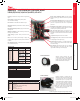
Housing is molded from strong mineral and glass lled
nylon.
Pointer stops of molded rubber prevent pointer
over-travel without damage.
Full view lens is removable and molded of acrylic.
Aluminum scale litho-printed black on white, enhances
readability.
Red tipped aluminum pointer, rigidly mounted to helix
is easy to see.
Wishbone assembly provides mounting for helix, helix
bearings, and pointer shaft.
Jewel bearings provide virtually friction-free helix
motion.
Helix is free to rotate in jewel bearings. It aligns with
magnetic eld of magnet to transmit pressure indications
to pointer.
Zero adjustment screw, located behind the removable
lens, eliminates tampering.
Range spring calibration clamp xes live length of
spring for proper gage calibration and is factory set and
sealed.
Silicone rubber diaphragm allows accurate response
to a broad range of temperatures and at extremely low
pressure. Incorporates blow out area for overpressure
protection.
Diaphragm support plates of lightweight aluminum on
each side of the diaphragm minimize position or attitude
sensitivity and help dene pressure area.
Flat leaf range spring reacts to pressure on the
diaphragm. Live length is adjustable for calibration. Small
amplitude of motion minimizes inaccuracies and assures
long life.
Low pressure tap connects to rear chamber.
Coil spring link provides a resilient connection between
the diaphragm and the range spring.
Ceramic magnet mounted on a molded bracket at the
end of the range spring rotates the helix without direct
mechanical linkage.
High pressure tap connects with the front chamber
through passageway in the plastic case and a sealing
ring molded into the edge of the diaphragm.
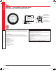
SURFACE MOUNTING
Optional surface mounting with back
mounting plate allows for quick installation
to any surface. Process connections are
barbed and point downwards. Add -BB for
bottom barbed surface mount option.
Mounting hardware is supplied with the
Minihelic
®
II gage for panel mounting through
a single hole, 2-5/8˝ (67 mm) in diameter.
Panel thickness up to 1/2˝ (13 mm) can be
accommodated with the hardware supplied.
If necessary, surface mounting of the gage
can be accomplished by means of two 4-40
screws into the tapped mounting bracket
stud holes in the rear of the gage. Surface
mounting requires clearance holes in the
panel for the two pressure taps.
PANEL MOUNTING
Process Tubing Options: See page 453 (Gage Tubing Accessories)
SERIES 2-5000
DWYER INSTRUMENTS, INC. | dwyer-inst.com
MODEL CHART
Model
Range,
Inches of Water Model
Range,
MM of Water
2-5000-0
2-5001
2-5002
2-5003
2-5005
2-5010
2-5020
2-5040
2-5060
2-5100
0-0.5
0-1.0
0-2.0
0-3.0
0-5.0
0-10
0-20
0-40
0-60
0-100
2-5000-25MM
2-5000-50MM
2-5000-100MM
0-25
0-50
0-100
Model
Range,
Pascals
2-5000-125PA
2-5000-250PA
2-5000-500PA
0-125
0-250
0-500
Model
Range,
kPa
Model Range, PSI 2-5000-1KPA
2-5000-3KPA
0-1
0-3
2-5205 0-5
ACCESSORIES
Model Description
A-302F-A
A-434
A-489
A-497
A-609
A-480
303 SS static pressure tip with mounting ange; for 3/16˝ ID rubber or
plastic tubing; 4˝ insertion depth; includes mounting screws
Portable kit
4˝ straight static pressure tip with ange
Surface mounting bracket
Air lter kit
Plastic static pressure tip
OPTIONS
To order add sufx: Description
-NPT 1/8˝ male NPT connections
Example: 2-5001-NPT
-BB Bottom barbed surface mount
Example: 2-5001-BB
-NIST NIST traceable calibration certicate
Example: 2-5001-NIST
-FC Factory calibration certicate
Example: 2-5001-FC
Pressure_2021.indb 27 7/15/20 8:15 AM