
Installtion Instruction
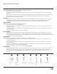
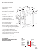

FIG.2
Fixture Wires
Black or
Smooth
Fixture Wires
White or
Ribbed
Fixture Wires
Bare Copper
(Ground)
House Wires
Black
(Hot)
House Wires
White
(Neutral)
House Wires
Green or Bare Copper
(Ground)
100%-10% DIMMING
COMPATIBLE WITH THE FOLLOWING ELECTRONIC
FIG.1PREPARATION
1. Shut o the power at the circuit breaker and
remove existing xture, including the
mounting hardware.
2. Carefully unpack your new xture and lay out
all the parts on a clear area. Be careful not to
lose any small parts necessary for installation.
MOUNTING THE FIXTURE (Fig. 1)
3. Remove the moutning screws (C1)
from the xture.
4. Carefully put the crystal (M1) into the
holder (L1) on xture (I1).
5. Place the end cover (J1) onto the
holder (K1), secure allen screws (D1) by using
provided allen wrench (N1).
6. Drill holes in the wall aligned with key-hole
location in the mounting plate (E1).
Insert the mounting anchors (G1).
7. Connect the xture to junction box wires as
shown in Fig. 2, making sure that all wire connectors (B1)
are secured. Fixture and junction box ground wires should be
connected to mounting plate using green screw provided.
After wires are connected, tuck them carefully inside the junction box.
8. Secure the mounting plate (E1) to the junction
box (F1) using junction box screws (A1). The side of the
mounting plate marked “GND” must face out.
9. Fasten the wood screws (H1) into the mounting anchors (G1).
Tighten the mounting plate (E1) on the wall.
MOUNTING THE FIXTURE (Fig. 1)
10. Place the xture (I1) over the mounting plate (E1) and secure with screws (C1).
F1
G1
E1
H1
A1
D1
N1
J1
I1
K1
M1
B1
C1
L1
Junction
box
Wire
connector
Mounting
screw
Bottom
holder
Mounting
anchor
Mounting
plate
Wood
screw
Junction
box screw
Allen
wrench
Allen screw
End cover
Fixture
Crystal
Top
Holder
INSTALLATION INSTRUCTION
LOW VOLTAGE (ELV) DIMMERS