DC-LINK-LR2 / DC-LINK-ULR1 Long Range Wireless HDMI/SDI HD Video Transmission Suite for Indoor use Manual / Handbuch
Introduction Congratulations on purchasing the DC-Link-ULR1 Video Transmission System. Please read this manual carefully before operating your product, and ensure it is kept in a safe place. The technology contained in this product, including the device itself as well as related software and trademarks, is protected by law. Any duplication or reproduction without the written permission of the copyright owner is prohibited, in part or in full.
ENGLISH Safety Precautions The Video Transmission System Do not block or obstruct air vents, as this may cause short circuits, fire or electric shocks. Turn the device off immediately if it comes into contact with liquids. The Power Supply The device may be used with batteries or AC-DC power supplies of the voltage specified on the device or in the enclosed documentation. If batteries are used, please ensure that the batteries are compatible and have no cracks or leaks.
Overview The DC-Link-ULR1 is a high-performance WHDI video transmission system which transmits uncompressed video and audio signals up to 1000m with low latency (1 ms delay). Due to the conscious decision not to implement the DFS (Dynamic Frequency Selection) System, which is compulsory for outdoor use, the device has a longer range, greater stability and better usability than comparable systems, but is only authorised for indoor use.
1 Characteristics Y e a r 1000m Range Transmission ranges of up to 1000m are possible with good line-of-sight and optimum antenna positioning Rapid and Reliable Connectivity The decision not to implement the DFS System compulsory for outdoor use, as well as the M a n u f a c t u r e r ’ s preinstalled transmission channels, mean there is no need for complex pairing procedures.
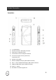
Product Description Transmitter: 1) ¼“ Tripod Mount 2) Antenna Connection: SMA (male) Connector 3) Menu button: Unlock/lock screen 4) Control button: Press to change the channels 5) LCD screen: Display channel, power level, temperature info. 6) 7) ON-OFF: Power Switch SDI-IN: 3G/HD/SD-SDI Input, (BNC Female Connector) 8) SDI LOOP-OUT: 3G/HD/SD-SDI Output, (BNC Female Connector) 9) HDMI-IN: HDMI Input (Type A Female Connector) 10) DC-IN: 9 – 18V DC 11) Mini USB: For firmware upgrade use.
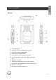
ENGLISH Product Description Receiver: 1) ¼“ Tripod Mount 2) Antenna Connection: RP-SMA (male) Connector 3) RSSI Status Display: Signal Strength 4) Menu button: Unlock/lock screen 5) Control button: Press to change the channels 6) LCD screen: Display channel, BAT voltage, temperature info. 7) ON-OFF: Power Switch 8) HDMI-OUT: HDMI Output (Type A Female Connector) 9) Dual SDI-OUT: 3G/HD/SD-SDI Output, (BNC Female Connector) 10) DC-IN: 9.0 – 18.0V DC 11) Mini USB: For firmware upgrade use.
Operation Transmitter 1. Connect the two omni-directional antennas to the SMA male connectors. 2. There is a ¼“ tripod mount at the base of the transmitter if required. 3. Use the enclosed 4-pin male-to-D-TAP cable to connect to a power supply with a suitable voltage. Receiver 1. There is a ¼“ tripod mount at the base of the receiver if required. 2. Use the enclosed 4-pin male-to-D-TAP cable to connect to a power supply with a suitable voltage. 3.
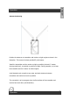
ENGLISH Operation Antenna Positioning Position the antennas on transmitter and receiver at right angles as shown in the illustration. This ensures the best possible RF performance. Install the transmitter and the receiver as high as possible (at least 1.5 metres above ground level), to maintain a good line-of-sight. During operation, try to keep the transmitter and the receiver at similar heights.
Choosing a Channel 1. To press and hold the “Menu” key with 2s, this unlock icon” ” shown on the OLED. 2. To press key “+” or “-“ to select this desired channel and then press this “MENU” key to confirm The system functions with 4 channels in the license-free 5 GHz ISM frequency band. Both the transmitter and the receiver have a frequency selector with positions from 1-4. Both the transmitter and the receiver have to be set to the same channel in or to communicate with each other.
ENGLISH Operation RSSI Display The RSSI (Wireless Received Signal Strength Indicator) display shows the strength of the signal, allowing the operator to ensure the system is working reliably.
Operation Establishing a Connection Once all previous steps have been performed, turn on the transmitter and the receiver using the power switch. Once the transmitter recognizes a video input, the video format will show on the LCD screen. It takes approximately 10-30 seconds for the transmitter to connect to the receiver. During this brief period, the receiver’s video out displays “Waiting for connection”.
Maintenance Please do not attempt to repair, modify or alter these devices under any circumstances. Clean the devices with a soft, clean, dry and lint-free cloth. Do not open the devices, they contain no user-serviceable parts. Storage The devices can be stored at temperatures between -20°C and 60°C. For long-term storage, please use the original transport case and avoid environmental conditions such as high humidity, dust, or excessively acidic or base surroundings.
ENGLISH Troubleshooting No video output Possible Cause Possible Solution Lack of power Check power supplies of transmitter and receiver and ensure that all cables are connected correctly and that there is sufficient Antennas power Ensure antennas are not damaged and are Video connection cable firmly connected Examine the transmitter’s “Video” LED display.
Technical Specifications Connections Transmitter Receiver 1x SDI Input (BNC female) 1x SDI Output (BNC female) 1x HDMI Input (Type A female) 2x Antenna (RP-SMA male) 2x SDI Output (BNC female) 1x HDMI Output (Type A female) 1x DC Input (4-pin female) Power 9.0 – 18.0V DC 5x Antenna (RP-SMA male) 1x DC Input (4-pin female) 9.0 – 18.0V DC Power Consumption <8W <8W Dimensions (LxBxH), w/o Antennas Weight 143.5 x 74.5 x 21.4mm 147.8 x 100 x 20mm 380g 540g Supported Video Formats 1080p(60, 59.
1x Qu ick sta rt Ma nu al Included with Purchase 1x Transmitter 1x Receiver ENGLISH 9x External Antennas (can be ordered individually) 2x DC Adapter Cables from Anton Bauer (D-Tap) (m) to 4-pin DC Connector(m) 2x Power Supplies 1x Magic-Arm with 1/4" Screw 1x Hot Shoe Adapter 2x Slot Screwdriver ! !17
Notes Vorwort !18 !
DwarfConnection OG Münzfeld 51, A-4810 Gmunden, Austria office@dwarfconnection.com www.dwarfconnection.com Errors and omissions excepted. Fehler und Änderungen vorbehalten.
FCC Warning This device complies with part 15 of the FCC rules. Operation is subject to the following two conditions: (1) this device may not cause harmful interference, and (2) this device must accept any inte rference received, including interference that may cause undesired operation. Changes or modifications not expressly approved by the party responsible for compliance could void the user's authority to operate the equipment.