
Installation manual

IOI-XTRK-10D Installation Manual
16
Relay Output Specifications
Maximum current 1A @ 24VDC
Maximum current 0.5A @ 125VAC
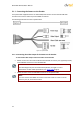
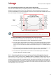
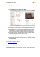
Relay Contact Schematic 5.1.2.1
Figure 8 - Relay Contact Schematic
NC: Terminal for connecting one of a pair of wires that leads to an external device
on a circuit configured for NORMALLY CLOSED
C: Terminal for connecting the second of a pair of wires for the COMMON lead of
an external device regardless of whether the device is operated in a NORMALLY
OPEN or NORMALLY CLOSED configuration
NO: Terminal for connecting one of a pair of wires that leads to an external device
on a circuit configured for NORMALLY OPEN
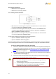
A relay output terminal has two options for connecting a device:
Option 1: NORMALLY CLOSED configuration
Option 2: NORMALLY OPEN configuration
The relay output supports an opto-isolated signal for a single external device, such as an electrical
door lock relay. Signals can be sent as continuous (ON/OFF) or single pulse of predefined duration.
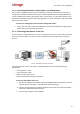
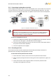
To connect a device controller to the unit’s relay output
1. Connect the leads from the external device controller to the respective terminal points
on the spring clamp terminal block according to your requirements (NORMALLY OPEN or
NORMALLY CLOSED configuration). See Connecting Leads to a Spring Clamp Terminal
Block (page 25) in the Appendix.
2. Insert the terminal block into the RELAY port on the front panel of the unit. See Figure 3
- IOI-XTRK-10D Front Panel (page 3).
3. Connect the other end of the cable to the external device, which receives the signal
from the unit and controls/powers the external device.
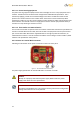
Caution:
1. To prevent damage to the unit, do not exceed the voltage and current
ratings for relay terminals.
2. To avoid damage to the system and system interference, a certified
electrician must ensure that the ground voltage (ground loops) is
comparable among all connected system components.