
Installation manual

Connections and Configuration
15
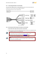
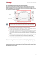
Connecting the Camera’s PTZ Control Line to the Encoder 5.1.1.2
Use a two-wire 24 AWG cable (not supplied by DVTEL) to enable the RS485 control connection
between the encoder and the camera. The cable attaches the terminal block connector on the
encoder’s RS232/485 port to the terminal block connector on the System Cable’s RS485 PTZ control
wires, according to the following illustration:
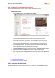
Figure 7 - Encoder-to-Camera Two-Wire Cable
Note:
The two-wire cable is not supplied by DVTEL and should be supplied by the installer.
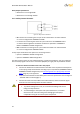
To connect the RS485 PTZ control line between the camera and encoder
1. Connect one end of the two-wire cable to the “D+” and “D-“ terminals (pins 1 and 2) on
the male 5-pin terminal block connector supplied with the encoder.
2. Insert the male 5-pin terminal block connector into the female terminal block connector
on the encoder, so that the “T+” and “T-“ terminals on the encoder align with the “D+”
and “D-“ wires on the two-wire cable’s terminal block. See Figure 3 - IOI-XTRK-10D Front
Panel.
3. Connect the other end of the two-wire cable to the “D+” and “D-” terminals (pins 1 and
5) on the male 5-pin terminal block connector supplied with the System Cable.
4. Insert the male 5-pin terminal block connector into the female 5-pin terminal block
connector attached to the System Cable.
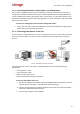
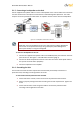
5.1.2 Connecting the Unit to Control an External Device (Using Relay Outputs)
External devices can be connected to the NORMALLY OPEN or NORMALLY CLOSED relay outputs of
the unit in order to enable a specific incident response or to automatically control a device via the
encoder in case of events such as intruder detection, poor signal, low visibility, etc. For example, if
an intruder is detected in a courtyard, as an automatic incident response exit doors are locked and
security shutters are closed. For more information on incident responses and relay outputs, refer to
the HTML Edition Units User’s Guide.