
Installation manual


IOI-XTRK-10D Installation Manual
4
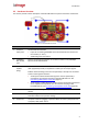
Figure 4 - Power Input Terminal
7
Terminal
block port 2
The terminal block includes a relay output, which supports output of opto-
isolated signal for a single external device, such as an electrical door lock
relay.
- NO: Terminal for NORMALLY OPEN configurations
- COM: Terminal for COMMON wire configurations for either NC or NO
- NC: Terminal for NORMALLY CLOSED configurations
For more information, see Connecting the Unit to Control an External Device
(Using Relay Outputs) (page 15).
8
VIDEO OUT
Video output for transmitting analog video signal to an analog video display or
analog video recording device. You can connect an analog monitor to view
real-time video of the camera.
9
GND (Ground)
External terminal on rear panel. See Grounding the Unit (page 18).
Relay Outputs 2.3
An external device, such as an electric door lock, can be connected to the RELAY terminal block of
the unit. In response to events such as poor visibility, signals can be sent to operate the external
device.
Caution :
1. To avoid damage to the system and system interference, a certified
electrician must ensure that the ground voltage is comparable (ground
loops) among all connected system components.
2. Consideration and care needs to be given regarding how the security
officers will reset, command, and override incident responses. For example,
if the system detects someone walking in a detection zone and
automatically executes a lockdown, security officers may need a bypass for
the lockdown.
RS485 Control Connection 2.4
The encoder supports one RS485 connection, which is used to control the camera. The RS485
connection to the unit is made through the TX+ and TX- lead wires on the camera’s System Cable.
Once connected, the PTZ camera can be remotely controlled from within the HTML Live View and
HTML setup application using its built-in PTZ Remote Control Panel. For more information, see
Connecting the Camera’s PTZ Control Line to the Encoder (page 15).