
Specifications

© Digital View Ltd 2010 www.digitalview.com Page 6 of 34
CONNECTION & OPERATION
CAUTION: Never connect or disconnect parts of the display system when the system is powered up as this may cause serious
damage.
CONNECTION
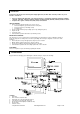
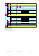
Connection and usage is quite straight forward (it is useful to have the relevant connection diagram available at this time):
1. LCD panel & Inverter: Connect the inverter (if it is not built-in the panel) to the CCFT lead connector of the LCD
panel.
2. LVDS type panels: Plug the LVDS signal cable direct to CN1 (if necessary). Insert the panel end of the cable to the
LCD panel connector.
3. TTL single pixel type panels: Plug the signal cables direct to CN2. Plug the other end of cables to the LCD
connector board (if connector board is required, otherwise the signal can be direct plug to the LCD panel
connector). Then plug the board connector to the LCD panel connector.
4. Inverter & Controller: Plug the inverter cable to CNB1 and CNA1 (if necessary). Plug another end to the connector
on the inverter.
5. Function switch & Controller: Plug the OSD switch mount cable to CNC1 on the controller board and another to
the OSD switch mount.
6. LED 1 : Plug in a 3-way with dual colour LED to connector LED1 on the controller board for indicating the controller
status.
7. LED 2 : Plug in a 3-way with dual color LED to connector LED2 on the controller board for indicating the backlight
status. This function is only available when CNB2 are proper connected and the panel is support the backlight status
function.
8. IR & Controller: Plug in a 3-way with IR sensor to connector IR1 on the controller board. (IR remote control function
support in V1.10.00 or up firmware revision)
9. Jumpers : Check all jumpers are set correctly. Details referring the connection diagram at
http://www.digitalview.com/controllers/csg.php
10. Jumpers & Inverter & Panel voltage: Particularly pay attention to the settings of JA3, JA6, JB2, JB3. JB2 & JB3
are used for inverter control (read inverter specification and information on the jumper table to define the correct
settings). JA3 & JA6 are used for panel voltage input (read panel specification and information on the jumper table to
define the correct settings).
11. DVI cable : Plug the DVI cable to the connector P2 on the controller board.
12. VGA cable : Plug the VGA cable to the connector P1 on the controller board.
13. Power supply & Controller: Plug the DC 12V / 24V power in to the connector PP2. You can consider to use
DigitalView mating power cable P/N 426013800-3, 160mm. Please read the jumper table in page 11-12 to define the
correct settings. Otherwise it may break down the panel.
14. Power on: Switch on the controller board and panel by using the OSD switch mount.
CAUTION: Never connect or disconnect parts of the display system when the system is powered up as this may cause serious
damage.
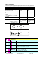
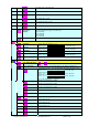
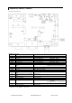
Controller LED status (LED1) :
State LED color
No signal & backlight off RED
No signal & backlight on ORANGE
With signal & backlight on GREEN
Backlight LED status (LED2) :
State LED color
Backlight fault RED
Backlight normal GREEN
General:
• If you are using supplied cables & accessories, ensure they are correct for the model of panel and controller.
• If you are making your own cables & connectors refer carefully to both the panel & inverter specifications and the section
in this manual, “Connectors, Pinouts & Jumpers” to ensure the correct pin to pin wiring.
PC SETTINGS
The controller has been designed to take a very wide range of input signals however to optimize the PC’s graphics performance
we recommend choosing 60Hz vertical refresh rate – this will not cause screen flicker.
OPERATION
Once the system has been connected and switched on there are a number of functions available to adjust the display
image as summarized in the following sections. The settings chosen will be saved for each mode independently.