
Specifications

© Digital View Ltd 2010 www.digitalview.com Page 17 of 34
3 Red LED pin (anode)
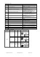
LED2 – Backlight status LED connector: 3-pin header
PIN DESCRIPTION
1 Green LED pin (anode)
2 LED pin common (cathode)
3 Red LED pin (anode)
IR1 – Infra-Red sensor connector: JST B3B-XH-A (Matching type : XHP-3) – Support in V1.10.00 or up firmware
revision.
PIN SYMBOL DESCRIPTION
1 GND Ground
2 STDBY_Vcc Stand by voltage
3 IR Data IR data
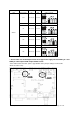
P1 - Analog VGA input – DB-15 way high density 3 row
PIN SYMBOL DESCRIPTION
1 PCR Red, analog
2 PCG Green, analog
3 PCB Blue analog
4 ID2 Reserved for monitor ID bit 2 (grounded)
5 DGND Digital ground
6 AGND Analog ground red
7 AGND Analog ground green
8 AGND Analog ground blue
9 DDC_5V +5V power supply for DDC (optional)
10 DGND Digital ground
11 ID0 Reserved for monitor ID bit 0 (grounded)
12 DDC_SDA DDC serial data
13 HS_IN Horizontal sync or composite sync, input
14 VS_IN Vertical sync, input
15 DDC_SCL DDC serial clock
P2 – DVI-D input
PIN SYMBOL DESCRIPTION
1 /RX2 TMDS Data 2-
2 RX2 TMDS Data 2+
3 GND Digital Ground
4 NC No connection
5 NC No connection
6 DVI_DDC_CLK DDC Clock
7 DVI_DDC_DAT DDC Data
8 DVI_VS_IN Analog vertical Sync
9 /RX1 TMDS Data 1-
10 RX1 TMDS Data 1+
11 GND Digital Ground
12 NC No connection
13 NC No connection
14 DVI_DDC_5V +5V power supply for DDC (optional)
15 GND Ground (+5, Analog H/V Sync)
16 NC No connection
17 /RX0 TMDS Data 0-
18 RX0 TMDS Data 0+
19 GND Digital Ground
20 NC No connection
21 NC No connection
22 GND Digital Ground
23 RXC TMDS Clock+
24 /RXC TMDS Clock-
25 NC No connection
26 NC No connection
PP2 – Alternate 12VDC power supply
PIN DESCRIPTION
1 +12VDC 5A max / +24VDC 5A max
2 Ground
PP5 - Power supply
PIN DESCRIPTION
1 +12VDC 5A max / +24VDC 5A max
2 Ground