NVR-52XX/58XX/60XX Series NVR
Regulatory information FCC information FCC compliance : This equipment has been tested and found to comply with the limits for a digital device, pursuant to part 15 of the FCC Rules. These limits are designed to provide reasonable protection against harmful interference when the equipment is operated in a commercial environment.
Preventive and Cautionary Tips Before connecting and operating your device, please be advised of the following tips: • • • • • Ensure unit is installed in a well-ventilated, dust-free environment. Unit is designed for indoor use only. Keep all liquids away from the device. Ensure environmental conditions meet factory specifications. Ensure unit is properly secured to a rack or shelf. Major shocks or jolts to the unit as a result of dropping it may cause damage to the sensitive electronics within the unit.
Product Key Features General Connectable to network cameras, network dome and DVS. Connectable to the third-party network cameras like AXIS, ONVIF, PANASONIC, PSIA, SAMSUNG and SANYO. PAL/NTSC adaptive video inputs. Each channel supports dual-stream. Up to 64 network cameras can be connected for NVR-6064 series NVR, 32 network cameras for NVR-6032, and 16 network cameras for NVR-5816XX.
Searching record files and captured pictures by events (alarm input/motion detection). Tag adding for record files, searching and playing back by tags. Locking and unlocking record files. Local redundant recording and capture. Provide new playback interface with easy and flexible operation. Searching and playing back record files by channel number, recording type, start time, end time, etc. Motion analysis for the selected area in the video. Zooming in when playback.
Support accessing by the platform via ONVIF. Remote search, playback, download, locking and unlocking of the record files, and support downloading files broken transfer resume. Remote parameters setup; remote import/export of device parameters. Remote viewing of the device status, system logs and alarm status. Remote keyboard operation. Remote locking and unlocking of control panel and mouse. Remote HDD formatting and program upgrading. Remote system restart and shutdown.
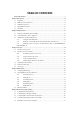
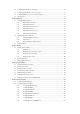
TABLE OF CONTENTS Product Key Features ............................................................................................................................. . 4 Chapter 1Introduction............................................................................................................................. ...... 11 1.1 Front Panel .................................................................................................................................... 12 1.
5.6 Configuring Holiday Record and Capture ..................................................................................... 72 5.7 Configuring Redundant Recording and Capture............................................................................ 74 5.8 Configuring HDD Group for Recording and Capture.................................................................... 76 5.9 Files Protection.......................................................................................................
.2.9 Configuring HTTPS Port .......................................................................................... 138 9.2.10 Configuring Email ................................................................................................... . 139 9.2.11 Configuring UPnP ................................................................................................... 140 9.2.12 Configuring High-speed Download .......................................................................... 142 9.
13.5 Managing User Accounts............................................................................................................. 185 13.5.1 Adding a User ........................................................................................................... 185 13.5.2 Deleting a User ........................................................................................................ . 187 13.5.3 Editing a User .............................................................................
Chapter 1 Introduction
1.1 Front Panel Figure 1. 1 NVR-6064 Table 1. 1 Description of Control Panel Buttons No. Name Function Description ALARM READY Turns red when a sensor alarm is detected. Ready indicator is normally blue, indicating that the device is functioning properly. Turns blue when device is controlled by an IR remote. STATUS Turns red when controlled by a keyboard and purple when IR remote and keyboard is used at the same time. HDD 1 Blinks red when data is being read from or written to HDD.
No. Name 6 Function Description USB Interfaces Universal Serial Bus (USB) ports for additional devices such as USB mouse and USB Hard Disk Drive (HDD). Back to the previous menu. ESC Press for Arming/disarming the device in Live View mode. Enter the Manual Record setting menu. REC/SHOT In PTZ control settings, press the button and then you can call a PTZ preset by pressing Numeric button. It is also used to turn audio on/off in the Playback mode. The button is used to enter the Playback mode.
No. Name Function Description camera. The DIRECTION buttons are used to navigate between different fields and items in menus. In the Playback mode, the Up and Down button is used to speed up and slow down recorded video. The Left and Right button DIRECTION will select the next and previous record files. In Live View mode, these buttons can be used to cycle through channels. 8 Control In PTZ control mode, it can control the movement of the PTZ Buttons camera.
No. Name Function Description The light is green when the IR remote control is enabled; STATUS The light is red when the function of the composite keys (SHIFT) are used; The light is out when none of the above condition is met. ALARM 2 The light is red when there is an alarm occurring. HDD Blinks red when HDD is reading/writing. Tx/Rx Blinks green when network connection is functioning normally. DVD-R/W Slot for DVD-R/W.
No. Name Function Description Check the checkbox and select the ON/OFF switch; Start/stop record clipping in playback. Enter numeral 6/MNO/PLAY Enter letters 6; MNO ; Playback, for direct access to playback interface. Enter numeral 7/PQRS/REC 7; Enter letters PQRS ; Open the manual record interface. Enter numeral 8/TUV/PTZ Enter letters 8; TUV ; Access PTZ control interface. 9/WXYZ/PRE V Enter numeral Enter letters Multi-channel display in live view.
STATUS: 1.The light is green when the IR remote control is enabled; 2.The light is red when the function of the composite keys (SHIFT) are used; 3. The light is out when none of the above condition is met/ ALARM: the light is red when there is an alarm occurring. HDD: the indicator flickers red when HDD is reading/writing. Tx/Rx: TX/RX indicator flickers green when network connection is functioning normally. Switch between the numeric or letter input and functions of the 3 composite keys.
Double press the button to switch the main and auxiliary output. In menu mode, the direction buttons are used to navigate between different fields and items and select setting parameters. In playback mode, the Up and Down buttons are used to speed DIRECTION up and slow down record playing, and the Left and Right buttons are used to move the recording 30s forwards or backwards. In the image setting interface, the up and down button can adjust the level bar of the image parameters.
1.2 IR Remote Control Operations The NVR may also be controlled with the included IR remote control, shown in Figure 1. 4. Note: Batteries (2 AAA) must be installed before operation. Figure 1. 4 Remote Control The keys on the remote control closely resemble the ones on the front panel. See Table 1.5. Table 1. 4 Description of the Soft Keyboard Icons No. Name Description 1 POWER Power on/off the device. 2 DEV Enables/Disables Remote Control.
Buttons 13 PTZ Button Same as the PTZ/IRIS- button on front panel. 14 ESC Button Same as the ESC button on front panel. 15 RESERVED Reserved for future usage. 16 F1 Button Same as the F1/LIGHT button on front panel. 17 PTZControl Buttons Buttons to adjust the iris, focus and zoom of a PTZ camera. 18 F2 Button Same as the F2/AUX button on front panel. Troubleshooting Remote Control: Note: Make sure you have installed batteries properly in the remote control.
1.3 USB Mouse Operation A regular 3-button (Left/Right/Scroll-wheel) USB mouse can also be used with this NVR. To use a USB mouse: 1. Plug USB mouse into one of the USB interfaces on the front panel of the NVR. 2. The mouse should automatically be detected. If in a rare case that the mouse is not detected, the possible reason may be that the two devices are not compatible, please refer to the recommended the device list from your provider. The operation of the mouse: Table 1.
1.4 Input Method Description Figure 1. 5 Soft Keyboard Description of the buttons on the soft keyboard: Table 1.
1.5 Rear Panel Figure 1. 6 NVR-6064 Table 1. 7 Description of Rear Panel Interfaces No. Item Description 1 VIDEO OUT BNC connector for video output. CVBS AUDIO OUT RCA connector for audio output. This connector is synchronized with CVBS video output. 2 VGA AUDIO OUT RCA connector for audio output. This connector is synchronized with VGA video output. 3 LINE IN BNC connector for audio input. 4 RS-232 Interface Connector for RS-232 devices. 5 VGA DB9 connector for VGA output.
Figure 1. 7 NVR-5832P8 Table 1. 8 Description of Rear Panel Interfaces No. Item Description 1 VIDEO OUT BNC connector for video output. 2 CVBS AUDIO OUT BNC connector for audio output. This connector is synchronized with CVBS video output. VGA AUDIO OUT BNC connector for audio output. This connector is synchronized with VGA video output. 3 LINE IN BNC connector for audio input. 4 RS-232 Interface Connector for RS-232 devices. 5 VGA DB9 connector for VGA output.
Table 1. 9 Description of Rear Panel Interfaces No. 1 Item Network Interfaces Description Network interface for the cameras and to provide power over Ethernet. with PoE function 2 VIDEO OUT BNC connector for video output. 3 AUDIO OUT BNC connector for audio output. 4 AUDIO IN 5 RS-232 Interface BNC connector for audio input. (Also for voice talk) Connector for RS-232 devices. 6 VGA DB9 connector for VGA output. Display local video output and menu. 7 HDMI HDMI video output connector.
Chapter 2 Getting Started
2.1 Starting Up and Shutting Down the NVR Purpose: Proper startup and shutdown procedures are crucial to expanding the life of the NVR. Before you start: Check that the voltage of the extra power supply is the same with the NVR s requirement, and the ground connection is working properly. Starting up the NVR: Steps: 1. Check the power supply is plugged into an electrical outlet. It is HIGHLY recommended that an Uninterruptible Power Supply (UPS) be used in conjunction with the device.
In the Shutdown menu, you can also reboot the NVR. Steps: 1. Enter the Shutdown menu by clicking Menu > Shutdown. 2. Click the Logout button to lock the NVR or the Reboot button to reboot the NVR.
2.2 Using the Wizard for basic configuration By default, the Setup Wizard starts once the NVR has loaded, as shown in Figure 2. 2. Figure 2. 2 Start Wizard Interface Operating the Setup Wizard: 1. The Setup Wizard can walk you through some important settings of the NVR. If you don t want to use the Setup Wizard at that moment, click the Cancel button. You can also choose to use the Setup Wizard next time by leaving the Start wizard when the device starts? checkbox checked. 2.
Figure 2. 4 Date and Time Settings 6. After the time settings, click Next button which takes you back to the Network Setup Wizard window, as shown in Figure 2. 5. NVR-6064 NVR-5816P8/7632P8 Figure 2.
Note: Dual-NIC is only supported in NVR-6064. And for NVR-5816P8/7632P8series NVR, the internal NIC IPv4 address should be configured for the cameras connecting to the PoE network interface of the NVR. 7. Click Next button after you configured the network parameters, which takes you to the HDD Management window, shown in Figure 2. 6. Figure 2. 6 HDD Management 8. To initialize the HDD, click the Init button. Initialization removes all the data saved in the HDD. 9. Click Next button.
Figure 2. 8 Record Settings 12. Click Copy to copy the settings to other channels, as shown in Figure 2. 9. Figure 2. 9 Copy Record Settings 13. Click OK to complete the startup Setup Wizard.
2.3 Adding and Connecting the IP Cameras 2.3.1 Adding the online IP Cameras Purpose: The main function of the NVR is to connect the network cameras and record the video got from it. So before you can get a live view or record of the video, you should add the network cameras to the connection list of the device. Before you start: Ensure the network connection is valid and correct.
Figure 2. 11 Edit the Parameters 2. Click apply to save the settings and click OK to exit the editing interface. To edit more parameters: 1. Click the Advance Set icon. Figure 2. 12 Network Configuration of the Camera 2. You can edit the network information and the password of the camera. Figure 2. 13 Password Configuration of the Camera 3. Click Apply to save the settings and click OK to exit the interface.
Explanation of the icons Edit basic parameters of the camera Delete the IP camera Get the live view of the camera Configuring the customized protocols Purpose: To connect the network cameras which are not configured with the standard protocols, you can configure the customized protocols for them. Steps: 1. Click the Protocol button to enter the protocol management interface. Figure 2. 14 Protocol Management Interface 2.
Figure 2. 15 Protocol Setting 4. Select the custom protocol and enter the IP address, user name and password of the camera. 5. Click the Add button to add the network camera. 2.3.3 Editing IP cameras connected to the PoE interfaces (Only for NVR-5816P8/7632P8 series NVR) The PoE interfaces enables the NVR system to pass electrical power safely, along with data, on Ethernet cabling to the connected network cameras.
Figure 2. 16 Edit IP Camera Interface - Plug-and-Play • Manual: You can disable the PoE interface by selecting the manual while the current channel can be used as a normal channel and the parameters can also be edited. Figure 2.
Chapter 3 Live View
3.1 Introduction of Live View Live view shows you the video image getting from each camera in real time. The NVR automatically enters Live View mode when powered on. It is also at the very top of the menu hierarchy, thus pressing the ESC many times (depending on which menu you re on) brings you to the Live View mode.
3.2 Operations in Live View Mode In live view mode, there are many functions provided. The functions are listed below. • • • Single Screen: showing only one screen on the monitor. Multi-screen: showing multiple screens on the monitor simultaneously. Auto-switch: the screen is auto switched to the next one. And you must set the dwell time for each screen on the configuration menu before enabling the auto-switch. Menu>Configuration>Live View>Dwell Time.
Switch between main Press Main/Aux button. and aux output 3.2.2 Using the Mouse in Live View Table 3. 4 Mouse Operation in Live View Name Description Menu Enter the main menu of the system by right clicking the mouse. Single Screen Switch to the single full screen by choosing channel number from the dropdown list. Multi-screen Adjust the screen layout by choosing from the dropdown list. Previous Screen Switch to the previous screen. Next Screen Switch to the next screen.
dropdown list. • Multi-screen: Switch between different display layout options. Layout options can be selected from a dropdown list. • Next Screen: When displaying less than the maximum number of cameras in Live View, clicking this feature will switch to the next set of displays. • Playback: Enter into Playback mode. • PTZ: Enter PTZ Control mode. • Main Monitor: Enter Main operation mode.
Figure 3. 3 Digital Zoom Image Settings icon can be selected to enter the Image Settings menu. Figure 3. 4 Image Settings- Preset You can also choose the Customize mode to set the image parameters like brightness, contrast, saturation and hue. Figure 3. 5 Image Settings- Customize Live View Strategy can be selected to set strategy, including Real-time, Balanced, Fluency.
Figure 3.
3.3 Adjusting Live View Settings Purpose: Live View settings can be customized according to different needs. You can configure the output interface, dwell time for screen to be shown, mute or turning on the audio, the screen number for each channel, etc. Steps: 1. Enter the Live View Settings interface. Menu> Configuration> Live View Figure 3. 7 Live View-General The settings available in this menu include: • Video Output Interface: Designates the output to configure the settings for.
1) Select a View mode in . 2) Select the small window, and double-click on the channel number to display the channel on the window. You can click button to start live view for all the channels and click live view. 3) Click the Apply button to save the setting.
3.4 Channel-zero Encoding Purpose: Sometimes you need to get a remote view of many channels in real time from web browser or CMS(Client Management System) software, in order to decrease the bandwidth requirement without affecting the image quality, channel-zero encoding is supported as an option for you. Steps: 1. Enter the Live View Settings interface. Menu> Configuration> Live View 2. Select the Channel-Zero Encoding tab. Figure 3. 9 Live View- Channel-Zero Encoding 3.
3.5 User Logout Purpose: After logging out, the monitor turns to the live view mode and if you want to do some operation, you need to enter user name and password tog in again. Steps: 1. Enter the Shutdown menu. Menu>Shutdown Figure 3. 10 Shutdown 2. Click Logout. Note: After you have logged out the system, menu operation on the screen is invalid. It is required to input a user name and password to unlock the system.
Chapter 4 PTZ Controls
4.1 Configuring PTZ Settings Purpose: Follow the procedure to set the parameters for PTZ. The configuring of the PTZ parameters should be done before you control the PTZ camera. Before you start: Check that the PTZ and the NVR are connected properly through RS-485 interface. Steps: 1. Enter the PTZ Settings interface. Menu >Camera> PTZ Figure 4. 1 PTZ- General 2. Choose the camera for PTZ setting in the Camera dropdown list. 3. Enter the parameters of the PTZ camera.
4.2 Setting PTZ Presets, Patrols & Patterns Before you start: Please make sure that the presets, patrols and patterns should be supported by PTZ protocols. 4.2.1 Customizing Presets Purpose: Follow the steps to set the Preset location which you want the PTZ camera to point to when an event takes place. Steps: 1. Enter the PTZ Control interface. Menu>Camera>PTZ>More Settings Figure 4. 2 PTZ- More Settings 2. Use the directional button to wheel the camera to the location where you want to set preset. 3.
4.2.2 Calling Presets Purpose: This feature enables the camera to point to a specified position such as a window when an event takes place. Call preset in the PTZ setting interface: Steps: 1. Enter the PTZ Control interface. Menu>Camera>PTZ>More Settings 2. Check the round icon of Call Preset. Figure 4. 4 PTZ- Call Preset 3. Choose the preset number. Call preset in live view mode: Steps: 1. Press the PTZ button on the front panel or click the PTZ Control icon the PTZ setting menu in live view mode.
2. Choose Camera in the list on the menu. 3. Double click the preset in the Preset list to call it. 4.2.3 Customizing Patrols Purpose: Patrols can be set to move the PTZ to different key points and have it stay there for a set duration before moving on to the next key point. The key points are corresponding to the presets. The presets can be set following the steps above in Customizing Presets. Steps: 1. Enter the PTZ Control interface. Menu>Camera>PTZ>More Settings 2.
You can also delete all the key points by clicking the trash icon Select a key point, then click or . button to adjust the order of the key points. Figure 4. 8 KeyPoints Deletion 4.2.4 Calling Patrols Purpose: Calling a patrol makes the PTZ to move according the predefined patrol path. Calling patrol in the PTZ setting interface: Steps: 1. In the PTZ setting interface. Menu> Camera> PTZ> More Settings 2. Select the patrol number, and then click 3. Click to stop it. to call the patrol.
Figure 4. 9 Calling Patrol Calling patrol in live view mode: Steps: 1. Press PTZ control on the front panel or on the remote, or click PTZ Control icon on the quick setting panel, to show the PTZ control panel. 2. Choose Patrol on the control bar. 3. Double click the patrol or select the patrol and click to call it. Figure 4. 10 PTZ Panel- Patrol 4.2.5 Customizing Patterns Purpose: Patterns can be set by recording the movement of the PTZ.
Menu>Camera>PTZ>More Settings 2. Choose pattern number in the option box. Figure 4. 11 PTZ- Pattern 3. Click and use your mouse to drag the image or click the eight directional buttons in the control box under the image to move the PTZ camera. The movement of the PTZ is recorded as the pattern. 4. Click to save the pattern. 4.2.6 Calling Patterns Purpose: Follow the procedure to move the PTZ camera according to the predefined patterns. Calling pattern in the PTZ setting interface Steps: 1.
Figure 4. 12 PTZ- Calling Pattern Call pattern in live view mode. Steps: 1. In the live view mode, press PTZ control on the front panel or on the remote control, or click PTZ Control icon on the quick setting panel. 2. And then choose Pattern on the control bar. 3. Double click the pattern or select the pattern and click to call it. Figure 4.
4.3 PTZ Control Panel In the Live View mode, you can press the PTZ Control button on the front panel or on the remote control, or choose the PTZ Control icon to enter the PTZ panel. Figure 4. 14 PTZ Panel Table 4.
Chapter 5 Record and Capture Settings
5.1 Configuring Encoding Parameters Purpose: By configuring the encoding parameters you can define the parameters which affect the image quality, such as the transmission stream type, the resolution and so on. Before you start: 1. Make sure that the HDD has already been installed. If not, please install a HDD and initialize it. (Menu>HDD>General) Figure 5. 1 HDD- General 2. Check the storage mode of the HDD 1) Click Advanced to check the storage mode of the HDD.
1) Select Record tab page to configure. You can configure the stream type, the resolution, and other parameters on your demand. • Pre-record: The time you set to record before the scheduled time or event. For example, when an alarm triggered the recording at 10:00, if you set the pre-record time as 5 seconds, the camera records it at 9:59:55. • Post-record: The time you set to record after the event or the scheduled time.
2) Configure the parameters. 3) Click Apply to save the settings. Note: The interval is the time period between two capturing actions. You can configure all the parameters on this menu on your demand.
5.2 Configuring Record/Capture Schedule Purpose: Set the record schedule, and then the camera automatically starts/stops recording according to the configured schedule. Note: In this chapter, we take the record schedule procedure as an example, and the same procedure can be applied to configure schedule for both recording and capture. To schedule the automatic capture, you need to choose the Capture tab in the Schedule interface. Steps: 1. Enter the Record Schedule interface. Menu>Record/Capture>Schedule 2.
You can click the button to set the accurate time of the schedule. II. To schedule an all-day recording, check the checkbox after the All Day item. Figure 5. 8 Edit Schedule III. To arrange other schedule, leave the All Day checkbox blank and set the Start/End time. Note: Up to 8 periods can be configured for each day. And the time periods can t be overlapped each other. Repeat the above edit schedule steps to schedule recording or capture for other days in the week.
Figure 5. 10 Draw the Schedule Descriptions of the color icons are shown in the figure below. Figure 5. 11 Descriptions of the color icons Click the Apply button to validate the settings. If the settings can also be used to other channels, click Copy, and then choose the channel to which you want to copy.
Figure 5.
5.3 Configuring Motion Detection Record and Capture Purpose: Follow the steps to set the motion detection parameters. In the live view mode, once a motion detection event takes place, the NVR can analyze it and do many actions to handle it. Enabling motion detection function can trigger certain channels to start recording, or trigger full screen monitoring, audio warning, notify the surveillance center and so on.
Figure 5. 15 Motion Detection Handling 5) Select the channels which you want the motion detection event to trigger recording. 6) Click Apply to save the settings. 7) Click OK to back to the upper level menu. 8) Exit the Motion Detection menu. 3. Edit the Motion Detection Record Schedule. For the detailed information of schedule configuration, see Chapter Configuring Record/Capture Schedule.
5.4 Configuring Alarm Triggered Record and Capture Purpose: Follow the procedure to configure alarm triggered recording or capture. Steps: 1. Enter the Alarm setting interface. Menu> Configuration> Alarm Figure 5. 16 Alarm Settings 2. Click Alarm Input. Figure 5. 17 Alarm Settings- Alarm Input 1) Select Alarm Input number and configure alarm parameters. 2) Choose N.O (normally open) or N.C (normally closed) for alarm type. 3) Check the checkbox for Setting 4) Click Handling. .
Figure 5. 18 Alarm Handling 5) Choose the alarm triggered recording channel. 6) Check the checkbox to select channel. 7) Click Apply to save settings. 8) Click OK to back to the upper level menu. Repeat the above steps to configure other alarm input parameters. If the settings can also be applied to other alarm inputs, click Copy and choose the alarm input number. Figure 5. 19 Copy Alarm Input 3. Edit the Alarm triggered record in the Record/Capture Schedule setting interface.
5.5 Manual Record and Continuous Capture Purpose: Follow the steps to set parameters for the manual record and continuous capture. Using manual record and continuous capture, you need to manually cancel the record and capture. The manual recording and manual continuous capture is prior to the scheduled recording and capture. Steps: 1. Enter the Manual settings interface. Menu> Manual Or press the REC/SHOT button on the front panel. Figure 5. 20 Manual Record 2.
5.6 Configuring Holiday Record and Capture Purpose: Follow the steps to configure the record or capture schedule on holiday for that year. You may want to have different plan for recording and capture on holiday. Steps: 1. Enter the Record setting interface. Menu>Record> Holiday Figure 5. 22 Holiday Settings 2. Enable Edit Holiday schedule. 1) Click to enter the Edit interface. Figure 5. 23 Edit Holiday Settings 2) Check the checkbox after Enable Holiday.
3) Select Mode from the dropdown list. There are three different modes for the date format to configure holiday schedule. 3. 4) Set the start and end date. 5) Click Apply to save settings. 6) Click OK to exit the Edit interface. Enter Record/Capture Schedule settings interface to edit the holiday recording schedule. See Chapter 5.2 Configuring Record/Capture Schedule.
5.7 Configuring Redundant Recording and Capture Purpose: Enabling redundant recording and capture, which means saving the record files and captured pictures not only in the R/W HDD but also in the redundant HDD, will effectively enhance the data safety and reliability. . Steps: 1. Enter HDD Information interface. Menu> HDD Figure 5. 24 HDD General 2. Select the HDD and click 1) to enter the Local HDD Settings interface. Set the HDD property to Redundancy. Figure 5.
Figure 5. 26 Encoding Record 2) Select Camera you want to configure in the drop-down list. 3) Check the checkbox of Redundant Record/Capture. 4) Click OK to save settings and back to the upper level menu. Repeat the above steps for configuring other channels.
5.8 Configuring HDD Group for Recording and Capture Purpose: You can group the HDDs and save the record files and captured pictures in certain HDD group. Steps: 1. Enter HDD setting interface. Menu>HDD Figure 5. 27 HDD General 2. Select Advanced on the left bar. Figure 5. 28 Storage Mode Check whether the storage mode of the HDD is Group. If not, set it to Group. For detailed information, please refer to Chapter 10.4 Managing HDD Group. 3. Select General in the left bar. Click 4.
4) Click Apply to save settings. Note: After having configured the HDD groups, you can configure the Recording and Capture settings following the procedure provided in Chapter 5.2-5.7.
5.9 Files Protection Purpose: You can lock the recorded files or set the HDD property to Read-only to protect the record files from being overwritten. Protect file by locking the record files: Steps: 1. Enter Export setting interface. Menu> Export Figure 5. 30 Export 2. 3. Select the channels you want to investigate by checking the checkbox to Configure the record type, file type start/end time. 4. Click Search to show the results. . Figure 5. 31 Export- Search Result 5. Protect the record files.
Figure 5. 32 Unlocking Attention Protect file by setting HDD property to Read-only Steps: 1. Enter HDD setting interface. Menu> HDD Figure 5. 33 HDD General 2. Click to edit the HDD you want to protect. Figure 5. 34 HDD General- Editing Note: To edit HDD property, you need to set the storage mode of the HDD to Group. See Chapter Managing HDD Group. 3. Set the HDD property to Read-only. 4. Click OK to save settings and back to the upper level menu. Notes: 1.
Chapter 6 Playback
6.1 Playing Back Record Files 6.1.1 Playing Back by Channel Purpose: Play back the recorded video files of a specific channel in the live view mode. Channel switch is supported. Instant playback by channel Steps: Choose a channel in live view mode using the mouse and click the button in the quick setting toolbar. Note: In the instant playback mode, only record files recorded during the last five minutes on this channel will be played back. Figure 6. 1 Instant Playback Interface Playback by channel 1.
Front Panel: press PLAY button to play back record files of the channel under single-screen live view mode. Under multi-screen live view mode, the recorded files of the top-left channel will be played back. Note: Pressing numerical buttons will switch playback to the corresponding channels during playback process. 2. Playback management. The toolbar in the bottom part of Playback interface can be used to control playing progress, as shown in Figure 6. 3. Figure 6.
Note: Playback progress bar: use the mouse to click any point of the progress bar or drag the progress bar to locate special frames. 6.1.2 Playing Back by Time Purpose: Play back video files recorded in specified time duration. Multi-channel simultaneous playback and channel switch are supported. Steps: 1. Enter playback interface. Menu>Playback 2. Check the checkbox of channel(s) in the channel list and then double-click to select a date on the calendar. Figure 6.
Figure 6. 6 Interface of Playback by Time Figure 6. 7 Toolbar of Playback by Time Table 6.
6.1.3 Playing Back by Event Search Purpose: Play back record files on one or several channels searched out by restricting event type (e.g. alarm input and motion detection). Steps: 1. Enter the Playback interface. Menu>Playback 2. Select the Event in the drop-down list on the top-left side. 3. Select Alarm Input or Motion as the event type, edit the Start time and End time. Figure 6. 8 Alarm Input Search Interface Figure 6. 9 Motion Search Interface 4.
Figure 6. 10 Search Result Bar(Alarm In and Motion) 5. Click button to play back the file. You can click the Back button to back to the search interface. Note: Pre-play and post-play can be configured. 6. Playback interface. The toolbar in the bottom part of Playback interface can be used to control playing process. Figure 6.
Figure 6. 12 Toolbar of Playback by Event Table 6.
Figure 6. 13 Interface of Playback by Time Click button to add default tag. Click button to add customized tag and input tag name. Note: Max. 64 tags can be added to a single video file. 3. Tag management. Click button to check, edit and delete tag(s). Figure 6. 14 Tag Management Interface Steps: 1. Select the Tag from the drop-down list in the Playback interface. 2. Choose channels, edit start time and end time, and then click Search to enter Search Result interface.
Figure 6. 15 Video Search by Tag 3. Click button to play back the file. You can click the Back button to back to the search interface. Note: Pre-play and post-play can be configured. Figure 6. 16 Interface of Playback by Tag Figure 6.
Table 6.
Figure 6. 19 Result of System Log Search 4. Playback interface. The toolbar in the bottom part of Playback interface can be used to control playing process. Figure 6. 20 Interface of Playback by Log 6.1.6 Playing Back External File Purpose: Perform the following steps to look up and play back files in the external devices. Steps: 1. Enter Tag Search interface. Menu>Playback 2. Select the External File in the drop-down list on the top-left side. The files are listed in the right-side list.
Figure 6.
6.2 Auxiliary Functions of Playback 6.2.1 Playing Back Frame by Frame Purpose: Play video files frame by frame, in case of checking image details of the video when abnormal events happen. Steps: • Using a Mouse: Go to Playback interface. If you choose playback of the record file: click button until the speed changes to Single frame and one click on the playback screen represents playback of one frame.
6.2.3 Reverse Playback of Multi-channel Purpose: You can play back record files of multi-channel reversely. Up to 16-ch (with 1280*720 resolution) simultaneous reverse playback is supported; up to 4-ch (with 1920*1080P resolution) simultaneous reverse playback is supported and up to 1-ch (with 2560*1920 resolution) reverse playback is supported. 1. Enter Playback interface. Menu>Playback 2. Check more than one checkboxes to select multiple channels and click to select a date on the calendar. Figure 6.
6.3 Picture Playback Purpose: Search and view captured pictures stored in HDD. Steps: 1. Enter Playback interface. Menu>Playback 2. Select the Picture in the drop-down list on the top-left side. Figure 6. 24 Interface of Playback by Picture 3. Choose channels, edit start time and end time, and then click Search to enter Search Result interface. 4. Choose a picture you want to view and click button. You can click the Back button to back to the search interface.
Figure 6. 25 Result of Picture Search 5. The toolbar in the bottom part of Playback interface can be used to control playing process. Figure 6. 26 Picture Playback Toolbar Table 6.
Chapter 7 Backup
7.1 Backing up Record Files 7.1.1 Quick Export Purpose: Export record files to backup device(s) quickly. Steps: 1. Enter Video Export interface. Menu>Export>Normal Choose the channel(s) you want to back up and click button. Note: The time duration of record files on a specified channel cannot exceed one day. Otherwise, the message box Max. 24 hours are allowed for quick export. will pop up. Figure 7. 1 Quick Export Interface 2. Click on the button to start exporting.
Figure 7. 3 Export Finished 3. Check backup result. Choose the record file in Export interface and click button to check it. Note: The Player player.exe will be exported automatically during record file export. Figure 7. 4 Checkup of Quick Export Result Using USB1-1 7.1.2 Backing up by Normal Video Search Purpose: The record files can be backup to various devices, such as USB devices (USB flash drives, USB HDDs, USB writer), SATA writer and e-SATA HDD.
Figure 7. 5 Normal Video Search for Backup 3. Select record files you want to back up. Click to play the record file if you want to check it. Check the checkbox before the record files you want to back up. Note: The size of the currently selected files is displayed in the lower-left corner of the window. Figure 7. 6 Result of Normal Video Search for Backup 4. Export. Click Export button and start backup. Note: If the inserted USB device is not recognized: • Click the Refresh button. • Reconnect device.
Figure 7. 7 Export by Normal Video Search using USB Flash Drive Stay in the Exporting interface until all record files are exported with pop-up message box finished . Figure 7. 8 Export Finished 5. Check backup result. Choose the record file in Export interface and click button to check it. Note: The Player player.exe will be exported automatically during record file export. Figure 7.
Backup using USB writer and SATA writer Steps: 1. Enter Export interface. Menu>Export>Normal 2. Set search condition and click Search button to enter the search result interface. Figure 7. 10 Normal Video Search for Backup 3. Select record files you want to back up. Click button to play the record file if you want to check it. Check the checkbox before the record files you want to back up. Note: The size of the currently selected files is displayed in the lower-left corner of the window. Figure 7.
Figure 7. 12 Export by Normal Video Search using USB Writer Stay in the Exporting interface until all record files are exported with pop-up message box finished . Figure 7. 13 Export Finished 5. Check backup result. Choose the record file in Export interface and click button to check it. Note: The Player player.exe will be exported automatically during record file export. Figure 7.
Backup using eSATA HDDs Steps: 1. Enter Record>Advanced and set the usage of eSATA HDD at Export . Menu>Record>Advanced Choose eSATA and set its usage at Export. Click Yes when pop-up message box System will reboot automatically if the usage of eSATA is changed. Continue? Note: The usages of eSATA HDD contain Record/Capture and Export. And changes in usage will take effective after rebooting the device. 2. Enter Export interface.
• Click the Refresh button. • Reconnect device. • Check for compatibility from vendor. You can also format SATA HDD via the device. Figure 7. 17 Export by Normal Video Search Using eSATA HDD Stay in the Exporting interface until all record files are exported with pop-up message Figure 7. 18 Export Finished 5. Check backup result. Choose the record file in Export interface and click button to check it. Note: The Player player.exe will be exported automatically during record file export.
Figure 7. 19 Checkup of Export Result Using eSATA HDD 7.1.3 Backing up by Event Search Purpose: Back up event-related record files using USB devices (USB flash drives, USB HDDs, USB writer), SATA writer or eSATA HDD. Quick Backup and Normal Backup are supported. Steps: 1. Enter Export interface. Menu>Export>Event 1) Select Alarm Input from the dropdown list of Event Type. 2) Select the alarm input No. and time. 3) Click Search button to enter the Search Result interface.
Figure 7. 21 Result of Event Search 2) Click Details button to view detailed information of the record file, e.g. start time, end time, file size, etc. Figure 7. 22 Event Details Interface 3. Export. Click the Export button and start back up. Note: If the inserted USB device is not recognized: • Click the Refresh button. • Reconnect device. • Check for compatibility from vendor. You can also format USB flash drive or USB HDDs via the device.
Figure 7. 23 Export by Event Using USB Flash Drive Stay in the Exporting interface until all record files are exported with pop-up message Figure 7. 24 Export Finished 4. Check backup result. Note: The Player player.exe will be exported automatically during record file export. Figure 7. 25 Checkup of Event Export Result Using USB Flash Drive Export finished .
7.1.4 Backing up Video Clips Purpose: You may also select video clips to export directly during Playback, using USB devices (USB flash drives, USB HDDs, USB writer), SATA writer or eSATA HDD. Steps: 1. Enter Playback interface. Please refer to Chapter 6.1 Playing Back Record Files. 2. During playback, use buttons and in the playback toolbar to start or stop clipping record file(s). 3. Quit Playback interface after finishing clipping and you will then be prompted to save the clips.
Figure 7. 28 Export Video Clips Using USB Flash Drive Stay in the Exporting interface until all record files are exported with pop-up message Export finished . Figure 7. 29 Export Finished 6. Check backup result. Note: The Player player.exe will be exported automatically during record file export. Figure 7.
7.2 Backing up Pictures Purpose: Back up pictures using USB devices (USB flash drives, USB HDDs, USB writer), SATA writer or eSATA HDD. Steps: 1. Enter Export interface. Menu>Export>Picture Select channel(s), image type, start time and end time, and click Search button to enter the Search Result interface. Figure 7. 31 Picture Search for Backup 2. Select pictures you want to back up. Check the checkbox before the pictures you want to back up and click Export button.
Figure 7. 33 Export Pictures Using USB Flash Drive Stay in the Exporting interface until all record files are exported with pop-up message Figure 7. 34 Export Finished 4. Check backup result. Figure 7. 35 Checkup of Picture Export Using USB Flash Drive Export finished .
7.3 Managing Backup Devices Management of USB flash drives, USB HDDs and eSATA HDDs. 1. Enter Search Result interface of record files. Menu>Export>Normal Set search condition and click Search button to enter Search Result interface. Note: At least one channel shall be selected. Figure 7. 36 Normal Video Search for Backup 2. Select record files you want to back up. Click Export button to enter Export interface. Note: At least one record file shall be selected. Figure 7.
Figure 7. 38 USB Flash Drive Management Management of USB writers and DVD-R/W 1. Enter Search Result interface of record files. Menu>Export>Normal Set search condition and click Search button to enter Search Result interface. Note: At least one channel shall be selected. Figure 7. 39 Normal Video Search for Backup 2. Select record files you want to back up. Click Export button to enter Export interface. Note: At least one record file shall be selected.
Figure 7. 40 Result of Normal Video Search for Backup 3. Backup device management. Click Erase button if you want to erase the files from a re-writable CD/DVD. Note: There must be a re-writable CD/DVD when you make this operation. Note: If the inserted USB writer or DVD-R/W is not recognized: • Click the Refresh button. • Reconnect device. • Check for compatibility from vendor. Figure 7.
Chapter 8 Alarm Settings
8.1 Setting Motion Detection Alarm Steps: 1. Enter Motion Detection interface of Camera Management and choose a camera you want to set up motion detection. Menu> Camera> Motion Figure 8. 1 Motion Detection Setup Interface 2. Set up detection area and sensitivity. Tick Enable Motion Detection , use the mouse to draw detection area(s) and drag the sensitivity bar to set sensitivity. Click button and set alarm response actions. 3.
Figure 8. 3 Set Arming Schedule of Motion Detection 5. Click Handling tab to set up alarm response actions of motion alarm (please refer to Chapter Setting Alarm Response Actions). 6. If you want to set motion detection for another channel, repeat the above steps or just click Copy in the Motion Detection interface to copy the above settings to it.
8.2 Setting Sensor Alarms Purpose: Set the handling method of an external sensor alarm. Steps: 1. Enter Alarm Settings of System Configuration and select an alarm input. Menu> Configuration> Alarm Select Alarm Input tab to enter Alarm Input Settings interface. Figure 8. 4 Alarm Status Interface of System Configuration 2. Set up the handling method of the selected alarm input. Check the Setting checkbox and click Handling button to set up its alarm response actions. Figure 8.
Figure 8. 6 Set Arming Schedule of Alarm Input Choose one day of a week and Max. eight time periods can be set within each day, and click Apply to save the settings. Note: Time periods shall not be repeated or overlapped. Repeat the above steps to set up arming schedule of other days of a week. You can also use Copy button to copy an arming schedule to other days. 5. Select Handling tab to set up alarm response actions of the alarm input (please refer to Chapter Setting Alarm Response Actions). 6.
inputs to copy the settings to them. Figure 8.
8.3 Detecting Video Loss Alarm Purpose: Detect video loss of a channel and take alarm response action(s). Steps: 1. Enter Video Loss interface of Camera Management and select a channel you want to detect. Menu> Camera> Video Loss Figure 8. 9 Video Loss Setup Interface 2. Set up handling method of video loss. Check the checkbox of Enable Video Loss Alarm , and click button to set up handling method of video loss. Figure 8. 10 Set Handling Method of Video Loss 3.
Figure 8. 11 Set Arming Schedule of Video Loss 4. Select Handling tab to set up alarm response action of video loss (please refer to Chapter Setting Alarm Response Actions). 5. Click the OK button to complete the video loss settings of the channel.
8.4 Detecting Video Tampering Alarm Purpose: Trigger alarm when the lens is covered and take alarm response action(s). Steps: 1. Enter Video Tampering interface of Camera Management and select a channel you want to detect video tampering. Menu> Camera> Tamper-proof Figure 8. 12 Tamper-proof Setup Interface 2. Set the video tampering handling method of the channel. Check the checkbox of Enable Tamper-proof . Drag the sensitivity bar and choose a proper sensitivity level.
3) Click Apply button to save the settings. Note: Time periods shall not be repeated or overlapped. Figure 8. 14 Set Arming Schedule of Video Tampering 4. Select Handling tab to set up alarm response actions of video tampering alarm (please refer to Chapter Setting Alarm Response Actions). 5. Click the OK button to complete the video tampering settings of the channel.
8.5 Handling Exceptions Alarm Purpose: Exception settings refer to the handling method of various exceptions, e.g. • • • • • • • HDD Full: The HDD is full. HDD Error: Writing HDD error or unformatted HDD. Network Disconnected: Disconnected network cable. IP Conflicted: Duplicated IP address. Illegal Login: Incorrect user ID or password. Abnormal Record/Capture: No space for saving recorded files or captured images. Array Exception: Abnormal virtual disks exist under array.
8.6 Setting Alarm Response Actions Purpose: Alarm response actions will be activated when an alarm or exception occurs, including Full Screen Monitoring, Audible Warning (buzzer), Notify Surveillance Center, Upload Picture to FTP, Trigger Alarm Output and Send Email. Full Screen Monitoring When an alarm is triggered, the local monitor (VGA, HDMI or BNC monitor) display in full screen the video image from the alarming channel configured for full screen monitoring.
2. Set up arming schedule of the alarm output. Choose one day of a week and up to 8 time periods can be set within each day. Note: Time periods shall not be repeated or overlapped. Figure 8. 17 Set Arming Schedule of Alarm Output 3. Repeat the above steps to set up arming schedule of other days of a week. You can also use Copy button to copy an arming schedule to other days. Click the OK button to complete the video tampering settings of the alarm output No. 4.
8.7 Triggering or Clearing Alarm Output Manually Purpose: Sensor alarm can be triggered or cleared manually. If Manually Clear is selected in the dropdown list of dwell time of an alarm output, the alarm can be cleared only by clicking Clear button in the following interface. Steps: Select the alarm output you want to trigger or clear and make related operations. Menu> Manual> Alarm Click Trigger/Clear button if you want to trigger or clear an alarm output.
Chapter 9 Network Settings
9.1 Configuring General Settings Purpose: Network settings must be properly configured before you operate NVR over network. Steps: 1. Enter the Network Settings interface. Menu >Configuration>Network 2. Select the General tab. NVR-6064 NVR-5816P8/7632P8 Figure 9. 1 Network Settings Interface Note: Dual-NIC configuration is only applicable for NVR-6064 series NVR. 3.
Multi-address Mode: The parameters of the two NIC cards can be configured independently. You can select LAN1 or LAN2 in the NIC type field for parameter settings. You can select one NIC card as default route. And then the system is connecting with the extranet the data will be forwarded through the default route. Net-fault Tolerance Mode: The two NIC cards use the same IP address, and you can select the Main NIC to LAN1 or LAN2.
9.2 Configuring Advanced Settings 9.2.1 Configuring PPPoE Settings Purpose: Your NVR also allows access by Point-to-Point Protocol over Ethernet (PPPoE). Steps: 1. Enter the Network Settings interface. Menu >Configuration> Network 2. Select the PPPoE tab to enter the PPPoE Settings interface, as shown in Figure 9. 3. Figure 9. 3 PPPoE Settings Interface 3. Check the PPPoE checkbox to enable this feature. 4. Enter User Name, Password, and Confirm Password for PPPoE access.
Figure 9. 4 DDNS Settings Interface 3. Check the DDNS checkbox to enable this feature. 4. Select DDNS Type. Five different DDNS types are selectable: IPServer, DynDNS, PeanutHull, NO-IP and EasyDDNS. • IPServer: Enter Server Address for IPServer. Figure 9. 5 IPServer Settings Interface • DynDNS: 1) Enter Server Address for DynDNS (i.e. members.dyndns.org). 2) In the NVR Domain Name text field, enter the domain obtained from the DynDNS website.
2) In the NVR Domain Name text field, enter the domain obtained from the NO-IP website (www.no-ip.com). 3) Enter the User Name and Password registered in the NO-IP website. Figure 9. 8 NO-IP Settings Interface 9.2.3 Configuring NTP Server Purpose: A Network Time Protocol (NTP) Server can be configured on your NVR to ensure the accuracy of system date/time. Steps: 1. Enter the Network Settings interface. Menu >Configuration> Network 2.
Menu >Configuration> Network 2. Select the SNMP tab to enter the SNMP Settings interface, as shown in Figure 9. 10. Figure 9. 10 SNMP Settings Interface 3. Check the SNMP checkbox to enable this feature. 4. Configure the following SNMP settings: • Trap Address: IP Address of SNMP host. • Trap Port: Port of SNMP host. 5. Click to save and exit the interface. Note: Before setting the SNMP, please download the SNMP software and manage to receive the device information via SNMP port.
Figure 9. 12 Configure Alarm Host 4. Click to save and exit the interface. 9.2.6 Configuring Multicast Purpose: The multicast can be configured to realize live view for more than 128 cameras through network for NVR-6064 series NVR. A multicast address spans the Class-D IP range of 224.0.0.0 to239.255.255.255. It is recommended to use the IP address ranging from 239.252.0.0 to 239.255.255.255. Steps: 1. Enter the Network Settings interface. Menu >Configuration> Network 2.
9.2.8 Configuring Server and HTTP Ports Purpose: You can change the server and HTTP ports in the Network Settings menu. The default server port is 8000 and the default HTTP port is 80. Steps: 1. Enter the Network Settings interface. Menu >Configuration> Network 2. Select the More Settings tab to enter the More Settings interface, as shown in Figure 9. 11. 3. Enter new Server Port and HTTP Port. Figure 9. 15 Host/Others Settings Menu 4. Enter the Server Port and HTTP Port in the text fields.
9.2.10 Configuring Email Purpose: The system can be configured to send an Email notification to all designated users if an alarm event is detected, etc., an alarm or motion event is detected or the administrator password is changed. Before configuring the Email settings, the NVR must be connected to a local area network (LAN) that maintains an SMTP mail server.
Enable SSL (optional): Click the checkbox to enable SSL if required by the SMTP server. Sender: The name of sender. Sender s Address: The Email address of sender. Select Receivers: Select the receiver. Up to 3 receivers can be configured. Receiver: The name of user to be notified. Receiver s Address: The Email address of user to be notified. Enable Attached Pictures: Check the checkbox of Enable Attached Picture if you want to send email with attached alarm images.
3. Check checkbox to enable UPnP . 4. Select the Mapping Type as Manual or Auto in the drop-down list. Task1: Auto If you select Auto, the Port Mapping items are read-only, and the external ports are set by the router automatically. Steps: 1) Click Apply button to save the settings. 2) You can click Refresh button to get the latest status of the port mapping. Figure 9.
Figure 9. 23 UPnP Settings Finished-Manual 9.2.12 Configuring High-speed Download Purpose: You can enable the High-speed Download function to widen the outgoing bandwidth of the device. In this way you can speed up the download of record files through IE browser or CMS software. Note: If you enable the high-speed download function, the local menu operation will be affected. It is recommended to disable this function after finishing the remote downloading of record files. Steps: 1.
9.3 Checking Network Traffic Purpose: You can check the network traffic to obtain real-time information of NVR such as linking status, MTU, sending/receiving rate, etc. Steps: 1. Enter the Network Traffic interface. Menu >Maintenance>Net Detect Figure 9. 26 Network Traffic Interface 2. You can view the sending rate and receiving rate information on the interface. The traffic data is refreshed every 1 second.
9.4 Configuring Network Detection Purpose: You can obtain network connecting status of NVR through the network detection function, including network delay, packet loss, etc. 9.4.1 Testing Network Delay and Packet Loss Steps: 1. Enter the Network Traffic interface. Menu >Maintenance>Net Detect 2. Click the Network Detection tab to enter the Network Detection menu, as shown in Figure 9. 27. Figure 9. 27 Network Detection Interface 3.
detect the backup device, please check whether it is compatible with the NVR. You can format the backup device if the format is incorrect. Figure 9. 29 Export Network Packet 4. Click to start exporting. 5. After the exporting is complete, click OK to finish the packet export, as shown in Figure 9. 30. Figure 9. 30 Packet Export Attention Note: Up to 1M data can be exported each time. 9.4.
Figure 9. 31 Network status checking If the network is normal the following message box pops out. Figure 9. 32 Network status checking result If the message box pops out with other information instead of this one, you can click show the quick setting interface of the network parameters. Figure 9.
Note: Dual-NIC configuration is only applicable for the NVR-6064 series NVR. 9.4.4 Checking Network Statistics Purpose: You can check the network status to obtain the real-time information of NVR. Steps: 1. Enter the Network Detection interface. Menu>Maintenance>Net Detect 2. Choose the Network Stat. tab. Figure 9. 34 Network Stat. Interface 3. Check the bandwidth of IP Camera, bandwidth of Remote Live View, bandwidth of Remote Playback, bandwidth of Net Receive Idle and bandwidth of Net Send Idle. 4.
Chapter 10 HDD Management
10.1 Initializing HDDs Purpose: A newly installed hard disk drive (HDD) must be initialized before it can be used with your NVR. Note: A message box pops up when the NVR starts up if there exits any uninitialized HDD. Figure 10. 1 Message Box of Uninitialized HDD Click Yes button to initialize it immediately or you can perform the following steps to initialize the HDD. Steps: 1. Enter the HDD Information interface. Menu > HDD> General Figure 10. 2 HDD Information Interface 2. Select HDD to be initialized.
Figure 10. 5 HDD Status Changes to Normal Note: Initializing the HDD will erase all data on it.
10.2 Managing Network HDD Purpose: You can add the allocated NAS or disk of IP SAN to NVR, and use it as network HDD. Steps: 1. Enter the HDD Information interface. Menu > HDD>General Figure 10. 6 HDD Information Interface 2. Click the Add button to enter the Add NetHDD interface, as shown in Figure 10. 7. Figure 10. 7 HDD Information Interface 3. Add the allocated NetHDD. 4. Select the type to NAS or IP SAN. 5. Configure the NAS or IP SAN settings.
Figure 10. 8 Add NAS Disk • Add IP SAN: 1) Enter the NetHDD IP address in the text field. 2) Click the Search button to search the available IP SAN disks. 3) Select the IP SAN disk from the list shown below. 4) Click the OK button to add the selected IP SAN disk. Note: Up to 1 IP SAN disk can be added. Figure 10. 9 Add IP SAN Disk 6. After having successfully added the NAS or IP SAN disk, return to the HDD Information menu. The added NetHDD will be displayed in the list.
10.3 Managing eSATA Purpose: When there is an external eSATA device connected to NVR, you can configure eSATA for the use of Record/Capture or Export, and you can manage the eSATA in the NVR. Steps: 1. Enter the Advanced Record Settings interface. Menu >Record>Advanced 2. Select the eSATA type to Export or Record/Capture from the dropdown list of eSATA. Export: use the eSATA for backup. Refer to Backup using eSATA HDDs in Chapter Backing up by Normal Video Search for operating instructions.
10.4 Managing HDD Group 10.4.1 Setting HDD Groups Purpose: Multiple HDDs can be managed in groups. Video from specified channels can be recorded onto a particular HDD group through HDD settings. Steps: 1. Enter the Storage Mode interface. Menu > HDD > Advanced 2. Set the Mode to Group, as shown in Figure 10. 13. Figure 10. 13 Storage Mode Interface 3. Click the Apply button and the following Attention box will pop up. Figure 10. 14 Attention for Reboot 4.
Figure 10. 15 Local HDD Settings Interface 7. Select the Group number for the current HDD. Note: The default group No. for each HDD is 1. 8. Click the OK button to confirm the settings. Figure 10. 16 ConfirmHDD Group Settings 9. In the pop-up Attention box, click the Yes button to finish the settings. 10.4.2 Setting HDD Property Purpose: The HDD property can be set to redundancy, read-only or read/write (R/W).
Figure 10. 17 Set HDD Property 3. Set the HDD property to R/W, Read-only or Redundancy. 4. Click the OK button to save the settings and exit the interface. 5. In the HDD Information menu, the HDD property will be displayed in the list. Note: At least 2 hard disks must be installed on your NVR when you want to set a HDD to Redundancy, and there is one HDD with R/W property.
10.5 Configuring Quota Mode Purpose: Each camera can be configured with allocated quota for the storage of recorded files or captured pictures. Steps: 1. Enter the Storage Mode interface. Menu > HDD > Advanced 2. Set the Mode to Quota, as shown in Figure 10. 18. Note: The NVR must be rebooted to enable the changes to take effect. Figure 10. 18 Storage Mode Settings Interface 3. Select a camera for which you want to configure quota. 4. Enter the storage capacity in the text fields of Max.
Figure 10. 20 Copy Settings to Other Camera(s) 6. Select the camera (s) to be configured with the same quota settings. You can also click the checkbox of IP Camera to select all cameras. 7. Click the OK button to finish the Copy settings and back to the Storage Mode interface. 8. Click the Apply button to apply the settings. Note: If the quota capacity is set to 0, then all cameras will use the total capacity of HDD for record and picture capture.
10.6 Checking HDD Status Purpose: You may check the status of the installed HDDs on NVR so as to take immediate check and maintenance in case of HDD failure. Checking HDD Status in HDD Information Interface Steps: 1. Enter the HDD Information interface. Menu > HDD>General 2. Check the status of each HDD which is displayed on the list, as shown in Figure 10. 21. Figure 10. 21 View HDD Status (1) Note: If the status of HDD is Normal or Sleeping, it works normally.
Figure 10.
10.7 HDD Detection Purpose: The device provides the HDD detection function such as the adopting of the S.M.A.R.T. and the Bad Sector Detection technique. The S.M.A.R.T. (Self-Monitoring, Analysis and Reporting Technology) is a monitoring system for HDD to detect and report on various indicators of reliability in the hopes of anticipating failures. S.M.A.R.T. Settings Steps: 1. Enter the S.M.A.R.T Settings interface. Menu > Maintenance >HDD Detect 2. Select the HDD to view its S.M.A.R.
Figure 10. 24 Bad Sector Detection Note: represents normal sector; represents bad sector detected by Bad Sector Detection; bad sector detected by recording. And you can click Error info button to see the detailed damage information. And you can also pause/resume or cancel the detection.
10.8 Configuring HDD Error Alarms Purpose: You can configure the HDD error alarms when the HDD status is Uninitialized or Abnormal. Steps: 1. Enter the Exception interface. Menu > Configuration > Exceptions 2. Select the Exception Type to HDD Error from the dropdown list. 3. Click the checkbox(s) below to select the HDD error alarm type (s), as shown in Figure 10. 25. Note: The alarm type can be selected to: Audible Warning, Notify Surveillance Center, Send Email and Trigger Alarm Output.
Chapter 11 Camera Settings
11.1 Configuring OSD Settings Purpose: You can configure the OSD (On-screen Display) settings for the camera, including date /time, camera name, etc. Steps: 1. Enter the OSD Configuration interface. Menu > Camera > OSD 2. Select the camera to configure OSD settings. 3. Edit the Camera Name in the text field. 4. Configure the Display Name, Display Date and Display Week by clicking the checkbox. 5. Select the Date Format, Time Format and Display Mode. Figure 11. 1 OSD Configuration Interface 6.
11.2 Configuring Privacy Mask Purpose: You are allowed to configure the four-sided privacy mask zones that cannot be viewed by the operator. The privacy mask can prevent certain surveillance areas to be viewed or recorded. Steps: 1. Enter the Privacy Mask Settings interface. Menu > Camera >Privacy Mask 2. Select the camera to set privacy mask. 3. Click the checkbox of Enable Privacy Mask to enable this feature. Figure 11. 2 Privacy Mask Settings Interface 4. Use the mouse to draw a zone on the window.
11.3 Configuring Video Parameters Steps: 1. Enter the Image Settings interface. Menu > Camera >Image Figure 11. 4 Image Settings Interface 2. Select the camera to set image parameters. 3. You can click on the arrow to change the value of each parameter. 4. Click the Apply button to save the settings.
Chapter 12 NVR Maintenance Management and
12.1 Viewing System Information 12.1.1 Viewing Device Information Steps: 1. Enter the System Information interface. Menu >Maintenance>System Info 2. Click the Device Info tab to enter the Device Information menu to view the device name, model, serial No. , firmware version and encode version. 12.1.2 Viewing Camera Information Steps: 1. Enter the System Information interface. Menu >Maintenance>System Info 2.
Figure 12. 2 Record Information Interface 12.1.4 Viewing Alarm Information Steps: 1. Enter the System Information interface. Menu >Maintenance>System Info 2. Click the Alarm tab to enter the Alarm Information menu to view the alarm information, as shown in Figure 12. 3. Figure 12.
12.1.5 Viewing Network Information Steps: 1. Enter the System Information interface. Menu >Maintenance>System Info 2. Click the Network tab to enter the Network Information menu to view the network information, as shown in Figure 12. 4. Figure 12. 4 Network Information Interface 12.1.6 Viewing HDD Information Steps: 1. Enter the System Information interface. Menu >Maintenance>System Info 2. Click the HDD tab to enter the HDD Information menu to view the HDD status, free space, property, etc.
Figure 12.
12.2 Searching & Export Log Files Purpose: The operation, alarm, exception and information of the NVR can be stored in log files, which can be viewed and exported at any time. Steps: 1. Enter the Log Search interface. Menu >Maintenance>Log Information Figure 12. 6 Log Search Interface 2. Set the log search conditions to refine your search, including the Start Time, End Time, Major Type and Minor Type. 3. Click the Search button to start search log files. 4.
Note: Up to 2000 log files can be displayed each time. 5. You can click the button of each log or double click it to view its detailed information, as shown in Figure 12. 8. And you can also click the button to view the related video files if available. Figure 12. 8 Log Details 6. If you want to export the log files, click the Export button to enter the Export menu, as shown in Figure 12. 9. Figure 12. 9 Export Log Files 7. Select the backup device from the dropdown list of Device Name. 8.
20110514124841logBack.txt. To export all the log files: Steps: 1. Enter the Log Information interface. Menu> Maintenance> Log Information> Log Export 2. Click the Log Export tab. Figure 12. 10 Log Export Interface 3. You can check the checkbox of the HDD. 4. Click the Export button to export all the log files stored in the HDD.
12.3 Importing/Exporting Configuration Files Purpose: The configuration files of the NVR can be exported to local device for backup; and the configuration files of one NVR can be imported to multiple NVR devices if they are to be configured with the same parameters. Steps: 1. Enter the Import/Export Configuration File interface. Menu > Maintenance >Import/Export Figure 12. 11 Import/Export Config File 2. Click the Export button to export configuration files to the selected local backup device. 3.
12.4 Upgrading System Purpose: The firmware on your NVR can be upgraded by local backup device or remote FTP server. 12.4.1 Upgrading by Local Backup Device Steps: 1. Connect your NVR with a local backup device where the update firmware file is located. 2. Enter the Upgrade interface. Menu >Maintenance>Upgrade 3. Click the Local Upgrade tab to enter the local upgrade menu, as shown in Figure 12. 12. Figure 12. 12 Local Upgrade Interface 4. Select the update file from the backup device. 5.
Figure 12. 13 FTP Upgrade Interface 3. Enter the FTP Server Address in the text field. 4. Click the Upgrade button to start upgrading. 5. After the upgrading is complete, reboot the NVR to activate the new firmware.
12.5 Restoring Default Settings Steps: 1. Enter the Default interface. Menu > Maintenance > Default Figure 12. 14 Restore Factory Default 2. Click the OK button to restore the default settings. Note: Except the network parameters (including IP address, subnet mask, gateway, MTU, NIC working mode, default route and server port), all other parameters of the device will be restored to factory default settings.
Chapter 13 Others
13.1 Configuring RS-232 Serial Port Purpose: The RS-232 port can be used in two ways: Parameters Configuration: Connect a PC to the NVR through the PC serial port. Device parameters can be configured by using software such as HyperTerminal. The serial port parameters must be the same as the NVR s when connecting with the PC serial port. Transparent Channel: Connect a serial device directly to the NVR.
13.2 Configuring General Settings Purpose: You can configure the BNC output standard, VGA output resolution, mouse pointer speed through the Menu > Configuration > General interface. Steps: 1. Enter the General Settings interface. Menu >Configuration> General 2. Select the General tab. Figure 13. 2 General Settings Interface 3. Configure the following settings: • Language: The default language used is English.
13.3 Configuring DST Settings Steps: 1. Enter the General Settings interface. Menu >Configuration>General 2. Choose DST Settings tab. Figure 13. 3 DST Settings Interface You can check the checkbox before the Auto DST Adjustment item. Or you can manually check the Enable DST checkbox, and then you choose the date of the DST period.
13.4 Configuring More Settings for Device Parameters Steps: 1. Enter the General Settings interface. Menu >Configuration>General 2. Click the More Settings tab to enter the More Settings interface, as shown in Figure 13. 4. Figure 13. 4 More Settings Interface 3. Configure the following settings: • Device Name: Edit the name of NVR. • Device No.: Edit the serial number of NVR. The Device No. can be set in the range of 1~255, and the default No. is 255.
13.5 Managing User Accounts Purpose: There is a default account in the NVR: Administrator. The Administrator user name is admin and the password is 12345. The Administrator has the permission to add and delete user and configure user parameters. 13.5.1 Adding a User Steps: 1. Enter the User Management interface. Menu >Configuration>User Figure 13. 5 User Management Interface 2. Click the Add button to enter the Add User interface. Figure 13. 6 Add User Menu 3.
• Operator: The Operator user level has permission of Two-way Audio in Remote Configuration and all operating permission in Camera Configuration by default. • Guest: The Guest user has no permission of Two-way Audio in Remote Configuration and only has the local/remote playback in the Camera Configuration by default. User s MAC Address: The MAC address of the remote PC which logs onto the NVR. If it is configured and enabled, it only allows the remote user with this MAC address to access the NVR. 4.
• Remote Log Search: Remotely viewing logs that are saved on the NVR. • Remote Parameters Settings: Remotely configuring parameters, restoring factory default parameters and importing/exporting configuration files. • • • • • Remote Camera Management: Remote adding, deleting and editing of the IP cameras. Remote Serial Port Control: Configuring settings for RS-232 and RS-485 ports. Remote Video Output Control: Sending remote button control signal.
13.5.3 Editing a User Steps: 1. Enter the User Management interface. Menu >Configuration>User 2. Select the user to be edited from the list, as shown in Figure 13. 9. 3. Click the icon to enter the Edit User interface, as shown in Figure 13. 10. Note: The admin user can also be edited. Operator and Guest Admin Figure 13. 10 Edit User Interface 4. Edit the corresponding parameters.
Appendix
Glossary • Dual Stream: Dual stream is a technology used to record high resolution video locally while transmitting a lower resolution stream over the network. The two streams are generated by the NVR, with the main stream having a maximum resolution of 4CIF and the sub-stream having a maximum resolution of CIF. • HDD: Acronym for Hard Disk Drive. A storage medium which stores digitally encoded data on platters with magnetic surfaces.
FAQ • Why does my NVR make a beeping sound after booting? The possible reasons for the warning beep on the NVR are as follows: a) There is no HDD installed in the NVR. b) The HDD is not initialized. c) HDD error To cancel the beeping sound and use the NVR without HDD, enter the Exception Settings interface. For detailed information, see Chapter Handling Exceptions Alarm.