Network Video Recorder User’s Manual 1
Table of Contents 1 2 Features and Specifications ......................................................................................................................... 10 1.1 Overview .................................................................................................................................................. 10 1.2 Features ................................................................................................................................................... 10 1.
5 System Capability........................................................................................................................................... 32 6 GUI Operation ................................................................................................................................................. 33 6.1 Login ......................................................................................................................................................... 33 6.
6.6.9 6.6.10 6.7 Display ............................................................................................................................................... 63 Default ................................................................................................................................................ 64 Advanced ................................................................................................................................................. 65 6.7.1 HDD Management ..
8.2.4 8.2.5 8.2.6 8.3 Preview Window Switch ................................................................................................................. 83 PTZ Control ...................................................................................................................................... 83 Color and More Setup ..................................................................................................................... 85 Configuration ...........................................
9 FAQ ................................................................................................................................................................ 120 10 Appendix A HDD Capacity Calculation ................................................................................................. 125 11 Appendix B Compatible SATA HDD ...................................................................................................... 126 12 Appendix C Compatible USB List ..................
Welcome Thank you for purchasing our network video recorder! This quick start guide is designed to be a reference tool for your system. Please open the accessory bag to check the items one by one in accordance with the list below. Contact your local retailer ASAP if something is missing or damaged in the bag.
Important Safeguards and Warnings 1.Electrical safety All installation and operation here should conform to your local electrical safety codes. We assume no liability or responsibility for all the fires or electrical shock caused by improper handling or installation. 2.Transportation security Heavy stress, violent vibration or water splash are not allowed during transportation, storage and installation. 3.Installation Keep upwards. Handle with care.
Before your operation please read the following instructions carefully. Installation environment Keep away from extreme hot places and sources; Avoid direct sunlight; Keep away from extreme humid places; Avoid violent vibration; Do not put other devices on the top of the NVR; Be installed in well ventilated place; do not block the vent.
1 Features and Specifications 1.1 Overview It is a high performance network video recorder. This series product support local preview, multiple-window display, recorded file local storage, remote control and mouse shortcut menu operation, and remote management and control function. All these functions support this series product to be used in various situations. This series product supports centre storage, front-end storage and client-end storage. The monitor zone in the front-end can be set in anywhere.
Network Monitor Window Split Record Backup Network Management Peripheral Equipment Management Auxiliary Through network, sending audio/video data compressed by IPC or NVS to client-ends, then the data will be decompressed and display. If bandwidth is big enough, latency is less than 500ms Support max 10 connections Transmit audio/video data by HTTP, TCP, UDP, MULTICAST, RTP/RTCP and etc. Transmit some alarm data or alarm info by SMTP. Support WEB access in WAN.
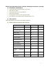
Operation System Embedded Linux real-time operation system Operation Interface WEB/Local GUI Video Compression H.264/MPEG4 Encode Capacity For H.264, it max supports 16*D1, 8*720,4*1080P. Audio Compression G.711a Video Output 1-channel VGA analog video output. Video Input 4/8/16-ch network compression digital video input HDMI 1-ch HDMI output. Audio Input Audio Output N/A 1-channel bidirectional talk output.
Network Connection Power Port Power Button Power Button IR Remote Control Receiver Clock One RJ45 10/100M/1000M self-adaptive Ethernet port. One power port, power adapter. Input DC 12V. One power port, AC100~240V 50+2% Hz. One power button in the rear panel. One power button in the front panel. N/A One IR remote control receiver in the front panel. Built-in clock. 16 record status indication lights One power status indication light. One alarm status indication light.
2 Front Panel and Rear Panel 2.1 Front Panel 2.1.1 1U Series The -1U series NVR front panel is shown as below. See Figure 2-1. Figure 2-1 Please refer to the following sheet for detail information. Name Icon Power button, press this button for three seconds to boot up or shut down NVR. Power button Number button Shift Function 0-9 Shift Input Arabic number Switch channel In textbox, click this button to switch between numeral, English(Small/Capitalized),donation and etc. Enable or disable tour.
Go to menu Record REC Slow play Manually stop/start recording, working with direction keys or numeral keys to select the recording channel. Multiple slow play speeds or normal playback. One-window monitor mode, click this button to display assistant function: PTZ control and image color. Backspace function: in numeral control or text control, press it for 1.5seconds to delete the previous character before the cursor.
Record light 1-16 It becomes on when system is recording. IR Receiver IR It is to receive the signal from the remote control. HDD abnormity HDD indicator Network abnormity indicator Net The red light is for the HDD abnormity The red light is for the network abnormity 2.1.2 2U Series The 2U series NVR front panel is shown as in Figure 2-2. Figure 2-2 Please refer to the following sheet for detail information.
Increase/decrease numeral. Assistant function such as PTZ menu. Left/ Right Shift current activated control, and then move left and right. When playback, click these buttons to control playback bar. Go to previous menu, or cancel current operation. ESC ESC When playback, click it to restore real-time monitor mode.
Reverse/Pause In normal playback or pause mode, click this button to reverse playback In reverse playback, click this button to pause playback. Play/Pause In normal playback click this button to pause playback In pause mode, click this button to resume playback. Window switch Mult Click it to switch one-window/multiple-window. In real-time monitor mode it works as left/right direction key. Playback mode, counter clockwise to forward and clock wise to backward.
2.2 Rear Panel 2.2.1 1 U Series The 1U series NVR real panel is shown as in Figure 2-3. Figure 2-3 Please refer to the following sheet for detailed information. Port Name Connection Function USB port. Connect to USB mouse. Network port 10M/100M self-adaptive Ethernet port. Connect to the network cable. RS232 232 debug COM. It is for general COM debug to configure IP address or transfer transparent COM data. HDMI High Definition Multimedia Interface High definition video signal output port.
Port Name NO1~NO3 Connection 1-3-ch alarm output port Function C1~C3 3 groups of alarm output ports. (Group 1: port NO1~C1,Group 2:port NO2~ C2,Group 3:port NO3~C3)).Output alarm signal to the alarm device. Please make sure there is power to the external alarm device. NO:Normal open alarm output port. A RS485 communication port C:Alarm output public end. RS485_A port. It is the cable A. You can connect to the control devices such as speed dome PTZ. B RS485_B.It is the cable B.
Port Name 1~16 Alarm input port. 1~16 Connection Function I/O port NO1~NO5 Four groups of alarm input ports. The first group is from port 1 to port 4, the second group is from port 5 to port 8, the third group is from 9 to 12, and the fourth group is from 13 to 16. They are to receive the signal from the external alarm source. There are two types; NO (normal open)/NC (normal close).
Port Name eSATA Connection Function Network port 10M/100M self-adaptive Ethernet port. Connect to the network cable. eSATA port The external SATA port. It can be connected to the peripheral devices of SATA port. Please pay attention to the HDD jumper when you connect the external HDD. USB port. Connect to USB mouse. RS232 232 debug COM. It is for general COM debug to configure IP address or transfer transparent COM data.
At the device end, speak via the speaker or the pickup, and then you can get the audio from the earphone or sound box at the pc-end. 2.3.2 PC-end to the device-end Device Connection Connect the speaker or the pickup to the audio output port in the PC and then connect the earphone or the sound box to the first audio input port in the device rear panel. Login the Web and then enable the corresponding channel real-time monitor. Please refer to the above interface (Figure 2-5) to enable bidirectional talk.
In input box, you can select input methods. Left click the corresponding button on the panel you can input numeral/English character (small/capitalized). Here ← stands for backspace button. _ stands for space button. In English input mode: _stands for input a backspace icon and ← stands for deleting the previous character. In numeral input mode: _ stands for clear and previous numeral. ← stands for deleting the When input special sign, you can click corresponding numeral in the front panel to input.
2.5 Remote Control The remote control interface is shown as in Figure 2-4 . Please note remote control is not our standard accessory and it is not included in the accessory bag. X282H282H282H X Figure 2-6 Please refer to the following sheet for detailed information. Serial Number Name Function 1 Power button Click it to boot up or shut down the device. 2 Address Click it to input device number, so that you can control it. 3 Forward Various forward speeds normal speed playback.
Next record In playback mode, playback the next video. Previous record In playback mode, playback the previous video. Play/Pause In pause mode, click this button to realize normal playback. 5 6 7 In normal playback click this button to pause playback. In real-time monitor mode, click this button to enter video search menu. Reverse/pause 8 Reverse playback pause mode, click this button to realize normal playback. In reverse playback click this button to pause playback.
and Video color. Switch the PTZ control menu in PTZ control interface. In motion detection interface, working with direction keys to complete setup. 15 0-9 number key Input password, switch channel. channel or Shift is the button to switch the input method.
3 HDD Installation For the first time install, please be aware that whether the HDDs have been installed. Strongly recommended to use the HDDs which we suggest you to use (high speed HDD that above 7200 rounds), we do not suggest you to use PC specified HDD. 3.1 1U Series Pleas follow the steps listed below to install the HDD. ① Remove screws on the ②Fix the four screws on the rear panel and the side panel. HDD (rotate three rounds) ③Place the HDD to the four holes.
3.2 2U Series ① Unscrew the screws on the rear panel and cover the upper cover. ② Place the HDDs on the HDD bracket and fix the HDD on the bracket with four screws. ③ Use data cable to connect main board and HDD port, then connect the power (the other end) cable to the HDD port. ④ After wires are connected, place the upper cover on the device and twist the screws on the rear panel.
Important Before you replace the HDD, please make sure you have shut down the device and unplug the power cable! 30
4 Network Connection 2U Series Connection Please refer to the following figure for 2U series connection. .
5 System Capability The max. system capability that this product series supports is 16-CH standard definition with transmission rate 2mbps every channel or 4-ch high definition with transmission rate 8mbps. The delay time for switch-in is under 500ms every channel. Model System capability 4-ch series Max. switch-in: 4-channel standard definition device with each channel max. supports 2 Mbps or 2-ch 720P or 1-ch 1080P. 8-ch series Max.
6 GUI Operation Connect the device to the monitor, insert the mouse and connect the power cable. Push the on/off button in the rear panel and then you can see the analog video output. You can use the mouse to implement some simple GUI operation. Please refer to the following chapter for detail information. All the operations listed below are based on our 16-ch series device. 6.1 Login After device booted up, the system is in multiple-channel display mode. See Figure 6-1.
Figure 6-2 6.2 Right Click Menu After you logged in the device, right click mouse, you can see the short cut menu. Please see Figure 6-3. Here you can set local playback window, PTZ control, video color, search records, remote device and etc. The local playback window includes 1/4/9/16. You can set the detail channel amount in 1/4-window. Figure 6-3 6.3 Main Menu After you logged in, the system main menu is shown as below. See Figure 6-4.
6.4 Search & Playback Click search button in the main menu, search interface is shown as below. See Figure 6-5. Usually there are three file types: R: Regular recording file. A: External alarm recording file. M: Motion detection recording file 2 1 3 4 11 7 6 5 10 8 12 9 Figure 6-5 Please refer to the following sheet for more information. SN 1 2 3 Name Function Display window Here is to display the searched picture or file. Support 1/4/9/16-window playback.
4 Playback mode and channel selection pane. 5 File list switch button 6 Card number search 7 Playback control pane. Playback mode:1/4/9/16. (It may vary due to different series.) In 1-window playback mode: you can select 1-16 channels. In 4-window playback mode: you can select 4 channels according to your requirement. In 9-window playback mode, you can switch between 1-9 and 10-16 channels. In 16-window playback mode, you can switch between1-16 and 17-32 channels.
Smart search The volume of the playback 8 Time bar Click the snapshot button in the full-screen mode, the system can snapshot 1 picture per second. It is to display the record type and its period in current search criteria. In 4-window playback mode, there are corresponding four time bars. In other playback mode, there is only one time bar. Use the mouse to click one point of the color zone in the time bar, system begins playback.
15 Digital zoom When the system is in full-screen playback mode, left click the mouse in the screen. Drag your mouse in the screen to select a section and then left click mouse to realize digital zoom. You can right click mouse to exit. Note: All the operations here (such as playback speed, channel, time and progress) have relationship with hardware version. Some series NVRs do not support some functions or playback speeds. 6.5 Information Here is for you to view system information.
Figure 6-7 In Figure 6-7, click view record d time button, HDD record time information interface is shown as in Figure 6-8. Figure 6-8 Parameter Function SATA 1-4 here means there are 4 HDDS. For 1U series product there are max 2 HDDs. For 2U series product there are max 8 HDDs. When HDD is working properly, system is shown as O. . ―_‖ means there is no HDD. SN You can view the HDD amount the device connected to; ﹡ means the second HDD is current working HDD. Type The corresponding HDD property.
Figure 6-9 6.5.3 Log Here is for you to view system log file. System lists the following information. See Figure 6-10. Log types include system operation, configuration operation, data management, alarm event, record operation, log clear and etc. Please select start time and end time, then click search button. You can view the log files. System max displays 100 logs in one page. It can max save 1024 log files. Please page up/down button to view if there are more than ten files.
Figure 6-11 6.5.4 Version Here is for you to view some version information. See Figure 6-12. Channel Alarm in Alarm out System version: Build Date Web Serial number Figure 6-12 6.5.5 Online Users Here is for you manage online users connected to the local device. See Figure 6-13. You can disconnect one user or block one user if you have proper system right.
Figure 6-13 6.6 Setting In main menu, highlight setting icon and double click mouse. System setting interface is shown as below. See Figure 6-14. Figure 6-14 Important Please note you need to have the proper right to implement the following operation. 6.6.1 General General setting includes the following items. See Figure 5-3 . System time: Here is for you to set system time Date format: There are three types: YYYYY-MM-DD: MM-DD-YYYYY or DD-MM-YYYY.
Language: System supports various languages: Chinese (simplified), Chinese (Traditional), English, Italian, Japanese, French, Spanish (All languages listed here are optional. Slight difference maybe found in various series.) HDD full: Here is for you to select working mode when hard disk is full. There are two options: stop recording or rewrite.
Figure 6-17 6.6.2 Encode Encode setting includes the following items. See Figure 6-18. Please note some series do not support extra stream. Channel: Select the channel you want. Type: Please select from the dropdown list. There are three options: regular/motion detect/alarm. You can set the various encode parameters for different record types. Compression: System supports H.264. Resolution: The mainstream resolution type is IPC’s encoding config. Generally there are D1/720P/1080P.
Figure 6-18 Figure 6-19 6.6.3 Schedule In the main menu, from setting to schedule, you can go to schedule menu. See Figure 6-20. Channel: Please select the channel number first. You can select “all” if you want to set for the whole channels. Week day: There are eight options: ranges from Saturday to Sunday and all. Pre-record: System can pre-record the video before the event occurs into the file. The value ranges from 1 to 30 seconds depending on the bit stream .
Figure 6-20 Shortcut settings: Users can copy the settings of channel A to channel B to achieve the same configuration effect.E.g. choose channel 1 and click the copy button after relevant settings are done, then paste to channel3, you can find that the configuration of channel3 is the same as that of channel1. Users can save the configuration of each channel respectively or save the configuration all at once ultimately. 6.6.4 RS232 RS232 interface is shown as below. There are five items. See Figure 6-21.
Figure 6-21 6.6.5 Network Here is for you to input network information. See Figure 6-22. IP address: Here you can input IP address. DHCP: It is to auto search IP. When enable DHCP function, you can not modify IP/Subnet mask /Gateway. These values are from DHCP function. If you have not enabled DHCP function, IP/Subnet mask/Gateway display as zero. You need to disable DHCP function to view current IP information. Besides, when PPPoE is operating, you can not modify IP/Subnet mask /Gateway.
Figure 6-22 6.6.5.1 Advanced Setup Advanced setup interface is shown as in Figure 6-23. Please draw a circle to enable corresponding function and then double click current item to go to setup interface. Figure 6-23 6.6.5.2 IP Filter IP filter interface is shown as in Figure 6-24. You can add IP in the following list. The list supports max 64 IP addresses. Please note after you enabled this function, only the IP listed below can access current NVR.
6.6.5.3 NTP Setup You need to install SNTP server (Such as Absolute Time Server) in your PC first. In Windows XP OS, you can use command ―net start w32time‖ to boot up NTP service. NTP setup interface is shown as in Figure 6-25. Host IP: Input your PC address. Port: This series NVR supports TCP transmission only. Port default value is 123. Update interval: minimum value is 1. Max value is 65535. (Unit: minute) Time zone: select your corresponding time zone here.
Figure 6-26 Here you can set a multiple cast group. Please refer to the following sheet for detailed information. IP multiple cast group address -224.0.0.0-239.255.255.255 -―D‖ address space The higher four-bit of the first byte=‖1110‖ Reserved local multiple cast group address -224.0.0.0-224.0.0.255 -TTL=1 When sending out telegraph -For example 224.0.0.1 All systems in the sub-net 224.0.0.2 All routers in the sub-net 224.0.0.4 DVMRP router 224.0.0.5 OSPF router 224.0.0.
Figure 6-27 6.6.5.6 DDNS Setup DDNS setup interface is shown as in Figure 6-28. You need a PC of fixed IP in the internet and there is the DDNS software running in this PC. In other words, this PC is a DNS (domain name server). In network DDNS, please select DDNS type and highlight enable item. Them please input your PPPoE name you get from you IPS and server IP (PC with DDNS ) . Click save button and then reboot system. Click save button, system prompts for rebooting to get all setup activated.
Status: When the UPNP is offline, it shows as ―Unknown‖. When the UPNP works it shows ―Success‖ Router LAN IP: It is the router IP in the LAN. WAN IP: It is the router IP in the WAN. Port Mapping list: The port mapping list here is the one to one relationship with the router’s port mapping setting. Enable Switch List: : :It shows that the function of port mapping is enabled in this port. Service name:Defined by user.
Figure 6-30 6.6.5.8 Email The email interface is shown as below. See Figure 6-31. SMTP server: Please input your email SMTP server IP here. Port: Please input corresponding port value here. User name: Please input the user name to login the sender email box. Password: Please input the corresponding password here. Sender: Please input sender email box here. Title: Please input email subject here. System support English character and Arabic number. Max 32-digit.
Figure 6-31 Figure 6-32 6.6.5.9 FTP You need to download or buy FTP service tool (such as Ser-U FTP SERVER) to establish FTP service. Please install Ser-U FTP SERVER first. From ―start‖ -> ―program‖ -> Serv-U FTP Server -> Serv-U Administator. Now you can set user password and FTP folder. Please note you need to grant write right to FTP upload user. See Figure 6-33. Figure 6-33 You can use a PC or FTP login tool to test setup is right or not. For example, you can login user ZHY to FTP://10.10.7.
Figure 6-34 System also supports upload multiple NVRs to one FTP server. You can create multiple folders under this FTP. In Figure 6-22, select FTP and then double click mouse. You can see the following interface. See Figure 6-35. Please highlight the icon in front of Enable to activate FTP function. Here you can input FTP server address, port and remote directory. When remote directory is null, system automatically create folders according to the IP, time and channel.
6.6.6 Alarm In the main menu, from Setting to Alarm, you can see alarm setup interface. See Figure 6-37. Alarm setup: Alarm interface is shown as below. See Figure 6-37. Alarm in: Here is for you to select channel number. Event type: There are two types. One is local input and the other is network input. Type: normal open or normal close. PTZ activation: Here you can set PTZ movement when alarm occurs. Such as go to preset, tour& pattern when there is an alarm.
Figure 6-37 Figure 6-38 Figure 6-39 Figure 6-40 57
6.6.7 Detect Go to Detect Menu In the main menu, from Setting to Detect, you can see motion detect interface. See Figure 6-41.There is three detection types: motion detection, video loss, camera masking. Motion Detect Detection menu is shown as below. See Figure 6-41 Event type: from the dropdown list you can select motion detection type. Channel: select the channel to activate recording function once alarm occurred.
Fn to switch between arm/withdraw motion detection. After setting, click enter button to exit.
Figure 6-44 Figure 6-45 Video Loss In Figure 6-41, select video loss from the type list. You can see the interface is shown as in CFigure 6-46.This function allows you to be informed when video loss phenomenon occurred. You can enable alarm output channel and then enable show message function. Tips: You can enable preset activation operation when video loss occurs. Please refer to chapter 4.5.2 motion detection for detailed information.
Camera Masking When someone viciously masks the lens, or the output video is in one-color due to the environments light change, the system can alert you to guarantee video continuity. Camera masking interface is shown as in Figure 6-47. Tips: You can enable preset/tour/pattern activation operation when video loss occurs. Please refer to chapter 4.5.2 motion detection for detailed information.
Channel: select the current camera channel. Protocol: select corresponding PTZ protocol(such as PELCOD) Address: default address is 1. Baud rate: select corresponding baud rate. Default value is 9600. Data bits: select corresponding data bits. Default value is 8. Stop bits: select corresponding stop bits. Default value is 1. Parity: there are three options: odd/even/none. Default setup is none. Figure 6-48 After completing all the setting please click save button.
Figure 6-50 Here is a sheet for you reference. Name Function key function Zoom Wide Focus Near Iris Close Shortcut key Function key function Far Shortcut Key │ Far ►│ Open 6.6.9 Display Display setup interface is shown as below. See Figure 6-51. Transparency: Here is for you to adjust transparency. The value ranges from 128 to 255. Channel name: Here is for you to modify channel name. System max support 25-digit (The value may vary due to different series).
Figure 6-51 In Figure 6-51, click modify button after channel. You can see an interface shown as in Figure 6-52. Please note all your modification here applies to local end only. You need to refresh web or client-end to get the latest channel name. System max support 25-digital character. Figure 6-52 In tour mode, you can see the following interface. On the right corner, right click mouse or click shift button, you can control the tour.
Please highlight icon to select the corresponding function. After all the setups please click OK button, system goes back to the previous menu. Warning! System menu color, language, time display mode, video format, IP address, user account will not maintain previous setup after default operation! 6.7 Advanced Double click advanced icon in the main window, the interface is shown as below. See Figure 6-54.
Figure 6-55 For the HDD group setup operation, please note: Each channel’s records can be stored into the specified HDD Group. Each HDD Group is corresponding to several hard disks, while one hard disk is only included in one HDD Group. Each channel is only corresponding with one HDD Group, while one HDD Group can store records from several channels. HDD Group is only available for read-write HDD and self-defined disks, other types of hard disks cannot be set as HDD Group.
Figure 6-56 In Figure 6-57, you can see the 6th and 7th position hard disks both belong to HDD Group 2. Important Once you change the HDD Group settings, system will pack the records and snapshots, and then reboot. Figure 6-57 Channels Setting Click the button named with ―Channels Settings‖ at the top right corner of the Figure 6-55, system will pop up an interface shown as in Figure 6-58.
The Figure 6-58 and Figure 6-59 show that channels 1 to 16 are associated to HDD Group NO 1, and channels 17 to 32 are associated to HDD Group NO 2. Therefore the records of channels 1 to 16 are stored into the hard disk(s) which belong to HDD Group NO 1, and the records of channels 17 to 32 are stored into the hard disk(s) which belong to HDD Group NO 2. Important Once you change the HDD Group settings, system will pack the records and snapshots, and then reboot. Figure 6-58 Figure 6-59 6.7.
Figure 6-60 6.7.3 Alarm Output Here is for you to set proper alarm output. Please highlight icon to select the corresponding alarm output. After all the setups please click OK button, system goes back to the previous menu. See Figure 6-61. Figure 6-61 6.7.4 Manual Record Note: You need to have proper rights to implement the following operations. Please make sure the HDD has been properly installed. 6.7.4.1 Manual record menu There are two ways for you to go to manual record menu.
There are three statuses: schedule/manual/stop. Please highlight icon “ ○ ” to select corresponding channel. Manual: The highest priority. After manual setup, all selected channels will begin ordinary recording. Schedule: Channel records as you have set in recording setup (Main Menu->Setting->Schedule) Stop: All channels stop recording. Figure 6-62 6.7.4.3 Enable/disable record Please check current channel status: ―○‖ means it is not in recording status, ―●‖ means it is in recording status.
Figure 6-64 All channel manual record Please highlight “ALL” after “Manual.” See Figure 6-65. When system is in manual recording, all scheduled set up you have set in will be null ((Main menu->Setting->Schedule)). You can see indication light in front panel turns on, system begins manual record now. Figure 6-65 6.7.4.5 Stop all channel recording Please highlight “ALL” after “Stop”. See Figure 6-66.
The user name and group name can consist of eight bytes. One name can only be used once. There are four default users: admin/888888/666666 and hidden user ―default‖. Except user 6666, other users have administrator right. Hidden user ―default‖ is for system interior use only and can not be deleted. When there is no login user, hidden user ―default‖ automatically login. You can set some rights such as monitor for this user so that you can view some channel view without login.
Figure 6-68 6.7.5.2 Add/Modify Group Click add group button, the interface is shown as below. See Figure 6-69. Here you can input group name and then input some memo information if necessary. There are total 60 rights such as control panel, shut down, real-time monitor, playback, record, record file backup, PTZ, user account, system information view, alarm input/output setup, system setup, log view, clear log, upgrade system, control device and etc. The modify group interface is similar to the Figure 6-69.
6.7.6 Auto Maintenance Here you can set auto-reboot time and auto-delete old files setup. You can set to delete the files for the specified days. See Figure 6-71. You can select proper setup from dropdown list. After all the setups please click save button, system goes back to the previous menu. Figure 6-71 6.7.7 Remote Device The remote device interface is shown as in Figure 6-72. Here you can set IPC IP address, port, remote device channel number, user name and its password.
The configuration file backup interface is shown as below. See Figure 6-73. This function allows you to copy current system configuration to other devices. Figure 6-73 6.8 Shutdown Double click shutdown button, system pops up a dialogue box for you to select. See Figure 6-74. Logout menu user: log out menu. You need to input password when you login the next time. Restart application: reboot device. Shutdown: system shuts down and turns off power. Restart system: system begins rebooting.
7 Quick Configuration Tool 7.1 Overview Quick configuration tool can search current IP address, modify IP address. At the same time, you can use it to upgrade the device. Please note the tool only applies to the IP addresses in the same segment. 7.2 Operation Double click the “ConfigTools.exe”icon, you can see an interface is shown as in Figure 7-1. In the device list interface, you can view device IP address, port number, subnet mask, default gateway, MAC address and etc.
Figure 7-2 Select the ―Open Device Web‖ item; you can go to the corresponding web login interface. See Figure 7-3. Figure 7-3 If you want to modify the device IP address without logging in the device web interface, you can go to the configuration tool main interface to set. In the configuration tool search interface (Figure 7-1), please select a device IP address and then double click it to open the login interface.
Figure 7-5 78
8 Web 8.1 General Introduction The device web provides channel monitor menu tree, search, alarm setup, system setup, PTZ control and monitor window. Important The following operation is based on 16-channel series device. 8.1.1 Preparation Before log in, please make sure: Step1: PC and NVR connection is OK. Step2: You have set PC IP address, NVR IP address, subnet mask and gateway. (Please set the IP address of the same section for the PC and NVR.
Figure 8-2 IE Safety Setup After installation, the interface is shown as below. See Figure 7-3. Figure 8-3 Login interface Please input your user name and password. Default factory name is admin and password is admin. Note: For security reasons, please modify your password after you first login. 8.2 Main Interface NVR web main interface is shown as in Figure 7-4.
② ③ ① ④ ⑤ ⑥ There are six sections: Section 1: Monitor channel menu tree Section 2: System menu Section 3: PTZ control Section 4: Video setup and other setup Section 5: Preview window Section 6: Monitor window switch 8.2.1 Monitor Channel Menu Tree The monitor channel menu tree is shown as in Figure 7-5. Figure 8-4 Monitor Channel Menu Tree Please refer to the following sheet for detailed information.
Parameter Function CAM 1 to CAM 16 channel 1 to channel 16 Open all /close all Click this button to open all video channels. Local play Click local play button to select file to play in PC. Refresh Click this button to refresh monitor channel name. Once all video channels are open, it becomes close all button. Please left click one monitor to view real-time video, the monitor window is shown as in Figure 8-5.
8.2.2 System Menu System menu is shown as in .Figure 7-7. Please refer to chapter 7.3 Configuration, chapter 7.4 Search, chapter 7.5 Alarm, chapter 7.6 About, chapter 7.7 Log out for detailed information. Figure 8-6 System Menu 8.2.3 Monitor Window Switch The monitor window switch interface is shown as in Figure 7-8. Figure 8-7 Monitor Window Switch System supports 1/4/6/8/9/13/16/20/25/36-window real-time preview. ----It is video quality adjustment button. It has relationship with decode via software.
You can click this icon to display or hide the PTZ control platform. Figure 8-9 PTZ Interface Click PTZ set button, the interface is shown as in Figure 7-11.
Please refer to the following sheet for PTZ setup information. Parameter Function Scan Move the camera to you desired location and then click left limit button. Then move the camera again and then click right limit button to set a right limit. Preset Use direction keys to move the camera to your desired location and then input preset value. Click add button, you have set one preset. Tour Input auto tour value and preset value. Click add button, you have added one preset in the tour.
It is to adjust monitor video contrast ness. All the operation here applies to WEB end only. It is to adjust monitor video saturation. It is to adjust monitor video hue. Reset Restore system default value. Click more button, the interface is shown as in Figure 8-12. Figure 8-12 Color and More Please refer to the following sheet for detailed information. Parameter Function More Picture Path Click picture path button, system pops up an interface for you to modify path.
Figure 8-13 Version Information 8.3.1.2 HDD information Here you can view local storage status such as free capacity and total capacity. See Figure 8-14. Figure 8-14 HDD Information 8.3.1.3 Log Here you can view system log.
Figure 8-15 Log Please refer to the following sheet for log parameter information. Parameter Function Type Log types include: system operation, configuration operation, data management, alarm event, record operation, user management, log clear and file operation. Start time Set time to start search. Finish time Set time to finish search Search You can select log type from the drop down list and then click search button to view the list.
8-16 Figure 8-16.
Figure 8-17 DST Figure 8-18 DST Please refer to the following sheet for detailed information. Parameter Function System Time Here is for you to modify system time. Please click Save button after your completed modification Sync PC You can click this button to save the system time as your PC current time. Data Format Here you can select data format from the dropdown list. Data Separator Please select separator such as – or /. Time Format There are two options: 24-H and 12-H.
8.3.2.2 Encode Figure 8-19 Parameter Function Channel Select the corresponding channel. Channel Name Display the current channel ID. You can also modify the channel ID here. Encoding mode The device does not support it. For the main stream, recorded file only contains video by default. You need to draw a circle here to enable audio function. Audio / video For extra stream, you need to draw a circle to select the video first and then select the audio if necessary.
Here you can privacy mask the specified video in the monitor video. One channel max supports 4 privacy mask zones. Overlay (Cover area) The privacy mask includes two options: Never/monitor. Never: It means do not enable privacy mask function. Monitor: the privacy mask zone can not be viewed in monitor mode. Time display You can enable this function so that system overlays time information in video window.
Figure 8-22 Copy Please refer to the following sheet for detailed information. Parameter Function Channel Please select a channel first. Pre-record Please input pre-record value here. When alarm record or motion detection record occurs, system can record the several seconds video before activating the record operation into the file. (Depends on data size). Setup In Figure 8-20, click set button, you can go to the corresponding setup interface.
Figure 8-23 RS232 Please refer to the following sheet for detailed information. Parameter Function RS232 There is only one option COM 01, corresponding to RS232. Function Console is for debug. Control keyboard: Switch between RS232 and control keyboard. Network keyboard: COM control protocol. You can use network keyboard to control NVR via COM. Transparent COM: Network user can communicate with RS232 COM device. PTZ matrix: PTZ matrix protocol. You can use the device to control the PTZ matrix.
Figure 8-24 Network Please refer to the following sheet for detailed information. Parameter Function Ethernet Please select the network card first. DHCP Dynamically get IP address. You can get the device IP from the DHCP server if you enabled this function. Device ID The ID for recognition in network TCP Port Default value is 37777. HTTP Port Default value is 80. UDP Port Default value is 37778. Max Connection Network user max amount. The value ranges from 1 to 10.
\ Figure 8-25 Network Parameter Remote host Function PPPOE Input the user name and password which ISP(Internet service supplier) provided and chose enable. Reboot system after configuration is saved and the device will auto connect to Internet. The IP address is the WAN IP. There are two conditions for reboot, 1. The user must have the authority to reboot device. 2.
Figure 8-26 Email Please refer to the following sheet for detailed information. Parameter Function SMTP Server Input server address and then enable this function. You can also input the corresponding server domain name here, but you need to go to DNS interface (chapter 7.3.4.1) to set the server IP that can parse the domain. SSL enable You can enable SSL encryption function to guarantee data safety. Port Default value is 25. You can modify it if necessary.
Figure 8-27 DDNS Please refer to the following sheet for detailed information. Parameter Function Server Type You can select DDNS protocol from the dropdown list and then enable DDNS function. The private DDNS protocol means you use our self-defined private protocol to realize DDNS function. Server IP DDNS server IP address Server Port DDNS server port. Domain Name Your self-defined domain name. User The user name you input to log in the server.
Figure 8-28 NAS Figure 8-29 NAS Setup Please refer to the following sheet for detailed information. Parameter Function NAS enable Please select network storage protocol and then enable NAS function. The network storage protocol includes FTP. Server IP Input remote storage server IP address. Port Input Remote storage server port number. User Name Log in user account. File length The max files length when you transfer the file. When the input value is 0, then system upload the whole files.
Parameter Function Password The password you need to login the server. Remote Path Remote storage file path. Channel Period info. Select a monitor channel . In NAS interface, click set button, you can go to the corresponding setup interface. See Figure 7-29 .Please set schedule period and then select corresponding record type: schedule/alarm. Please note device does not support motion detect record function now. Please select date (Current setup applies to current day by default.
Parameter Function Enable Enable NTP function or not. Server IP Server IP address Port Server port. System supports TCP only and default port value is 123. Time Zone Device current time zone. Update Interval Time update interval value. Alarm Centre Alarm centre interface is shown as below. Please input alarm centre server IP, port number. Once there is an alarm occurred, system can notify the alarm centre as you specified here.
Figure 8-32 UNPN 8.3.2.6 Alarm Alarm setup interface is shown as in Figure 8-33.
Figure 8-34 PTZ Setup Figure 8-35 Please refer to the following sheet for detailed information. Parameter Function Event Type It includes local alarm/network alarm/other. Alarm in Select corresponding alarm channel. Enable You need to draw a circle here so that system can detect the alarm signal. Type There are two options: normal open and normal close. NO becomes activated in low voltage, NC becomes activated in high voltage. Local alarm: Device detects alarm from input port.
Parameter Function Period Alarm record function becomes activated in the specified periods. There are six periods in one day. Please draw a circle to enable corresponding period. Select date. If you do not select, current setup applies to today only. You can select all week column to apply to the whole week. Click OK button, system goes back to alarm setup interface, please click save button to exit. Anti-dither System only memorizes one event during the anti-dither period.
Figure 8-36 Detect Parameter Function Event type Motion detect, video loss and video masking Channel select the channel to activate recording function Sensitivity System supports 6 levels. The sixth level has the highest sensitivity. Enable button Tick to enable There are PAL22X18/NTSC22X15 small zones. Region Blue area is the detection zone. Right click to view in full screen, click OK before exit to save the setup. Period Here you can set for business day and non-business day.
Parameter Function tour &pattern when there is an alarm. 8.3.2.2 PTZ PTZ interface is shown as in Figure 8-37 Please note, before operation please make sure you have set speed dome address and the NVR and speed dome connection is OK. Figure 8-37 PTZ Please refer to the following sheet for detailed information. Parameter Function Channel You can select monitor channel from the dropdown list. . Protocol Select the corresponding dome protocol.(such as PELCOD) Address Set corresponding dome address.
Please note system can not restore some information such as network IP address. Figure 8-38 Default and Backup Please refer to the following sheet for detailed information. Parameter Function Select All Restore factory default setup. Export Configuration Export system configuration to local PC. Import Configuration Import configuration from PC to the system. 8.3.3 Advanced 8.3.3.1 HDD Management Please select the storage device first and then you can see the items on your right become valid.
Figure 8-39 HDD Management Please refer to the following sheet for detailed information. Parameter Function Format Clear data in the HDD. Read/write Set current HDD as read/write Read only Set current HDD as read. Redundant Set current HDD as redundant HHD. Recover Fix the HDD error. Right now the device does not support this function.
8.3.3.2 Abnormity Parameter Function Event Type The abnormal events include: no disk, no space, disk error, offline, IP conflict. You need to draw a circle to enable this function. Threshold: It refers to the HDD free space.
Parameter Function Normal Out The corresponding alarm output channel when alarm occurs. For 1U series product, there are three channels. For 2U series product, there are six channels. The 6th channel is the controllable +12V alarm output. Latch The alarm output can delay for the specified time after alarm stops. The value ranges from 10s to 300s. Record channel After you selected the disk connection option, once the device is offline, the activated channel can begin alarm record.
Parameter Function Alarm output For 1U series product, there are three channels. For 2U series product, there are six channels. The 6th channel is the controllable +12V alarm output. Please click the corresponding number and then click the trigger button. Trigger Enable/disable alarm output. Please note once you activate an alarm manually, you need to click the output channel number again and then click trigger button to disable it. Otherwise the alarm can not be cancelled.
8.3.3.5 Account Here you can add, remove user or modify password. See Figure 8-42.
Parameter Function User Input the user name of the new established account. Reusable The reusable account means that this account can be used in more than one PC at the same time. Password Input the password of the new established account. Confirm Input the password of the new established account again. Group Select the group which the new account belongs to.
8.3.3.7 Remote device Figure 8-45 Remote device Parameter Function Channel Please select the local device channel number to connect to the remote device.. You need to highlight the enable item to activate this function. Now you can see remote device type, IP address and etc. Resolution type Choose the remote resolution type IP address, port, remote channel. Please input remote device IP address, port number, remote device channel number and account.
Figure 8-46 Auto register 8.3.4.2 DNS Here you can set server or local operator DNS address. See Figure 3-34. Once you input the domain name in SMTP server in the email interface (chapter 7.3.2.4 Network->email), you need to input the corresponding address here, otherwise the device can not parse the domain name.
8.4 Search Click search button, you can see an interface is shown as in Figure 8-48. Please select record playback mode, and then select start time, end time and channel. Then please click search button, you can see the corresponding files in the list. Select the file(s) you want to download and then click download button, system pops up a dialogue box , and then you can specify file name and path to download the file(s) to your local pc. Click OK to complete the download procedure.
Type Parameters Operation Multiplechannel playback Parameter Function Alarm Search alarm record. Motion Detection Search motion detection record. This function is not available in current device. Local Search local record. Snapshot Search snapshot file. This function is not available in current device. Card This function is not available in current device. Start time Set the file start time. End time Set the file end time. Channel Select the channel from the dropdown list.
Figure 8-49 Alarm Please refer to the following sheet for detailed information. Type Parameter Function Alarm Type Video loss System alarms when video loss occurs. This function is not available in current device. Motion detection System alarms when motion detection alarm occurs, This function is not available in current device. Disk full System alarms when disk is full. Disk error System alarms when disk error occurs. Camera masking System alarms when camera is viciously masking.
Type Parameter Function Path Here you can specify alarm sound file. 8.6 About Click about button, you can view the web information. See Figure 7-47. Figure 8-50 About 8.7 Log out Click log out button, you can go back to log in interface. See Figure 7-48.
9 FAQ 1. Device can not boot up properly. There are following possibilities: Input power is not correct. Power connection is not correct. Power switch button is damaged. Program upgrade is wrong. HDD malfunction or something wrong with HDD ribbon. Seagate DB35.1,DB35.2,SV35 or Maxtor 17-g has compatibility problem. Please upgrade to the latest version to solve this problem. Front panel error. Main board is damaged. 2. Device often automatically shuts down or stops running.
Device color or brightness setup is not correct. 6. Can not search local records. There are following possibilities: HDD ribbon is damaged. HDD is broken. Upgraded program is not compatible. The recorded file has been overwritten. Record function has been disabled. 7. Video is distorted when searching local records. There are following possibilities: Video quality setup is too low. Program read error, bit data is too small. There is mosaic in the full screen.
PTZ decoder and device address is not compatible. When there are several decoders, please add 120 Ohm between the PTZ decoder A/B cables furthest end to delete the reverberation or impedance matching. Otherwise the PTZ control is not stable. The distance is too far. 12. Motion detection function does not work. There are following possibilities: Period setup is not correct. Motion detection zone setup is not correct. Sensitivity is too low. For some versions, there is hardware limit.
System uses too much CPU resources. Please stop record first and then begin backup. Data amount exceeds backup device capacity. It may result in burner error. Backup device is not compatible. Backup device is damaged. 17. Keyboard can not control device. There are following possibilities: Device serial port setup is not correct Address is not correct When there are several switchers, power supply is not enough. Transmission distance is too far. 18.
There is no DivX503Bundle.exe control when you play the file transformed to AVI via media player. No DivX503Bundle.exe or ffdshow-2004 1012 .exe in Windows XP OS. 23. I forgot local menu operation password or network password Please contact your local service engineer or our sales engineer for help. We can guide you to solve this problem. 24. There is no video. The screen is in black. There are following possibilities: IPC IP address is not right. IPC port number is not right.
10 Appendix A HDD Capacity Calculation Calculate total capacity needed by each device according to video recording (video recording type and video file storage time). Step 1: According to Formula (1) to calculate storage capacity q i that is the capacity of each channel needed for each hour, unit Mbyte.
11 Appendix B Compatible SATA HDD Manufacturer Series Model Capacity Port Mode Seagate Barracuda.10 ST3750640AS 750G SATA Seagate Barracuda.10 ST3500630AS 500G SATA Seagate Barracuda.10 ST3400620AS 400G SATA Seagate Barracuda.10 ST3320620AS 320G SATA Seagate Barracuda.10 ST3250620AS 250G SATA Seagate Barracuda.10 ST3250820AS 250G SATA Seagate Barracuda.10 ST3160815AS 160G SATA Seagate Barracuda.10 ST380815AS 80G SATA Seagate Barracuda.
Westem Digital Cariar WD800BD 80G SATA Westem Digital Cariar SE16 WD7500KS 750G SATA Westem Digital Cariar SE16 WD5000KS 500G SATA Westem Digital Cariar SE16 WD4000KD 400G SATA Westem Digital Cariar SE16 WD3200KS 320G SATA Westem Digital Cariar SE16 WD2500KS 250G SATA 127
12 Appendix C Compatible USB List Manufacturer Model Capacity Sandisk Cruzer Micro 512M Sandisk Cruzer Micro 1G Sandisk Cruzer Micro 2G Sandisk Cruzer Freedom 256M Sandisk Cruzer Freedom 512M Sandisk Cruzer Fredom 1G Sandisk Cruzer Freedom 2G Kingston Data Traveler II 1G Kingston Data Traveler II 2G Kingston Data Traveler 1G Kingston Data Traveler 2G Maxell USB Flash Stick 128M Maxell USB Flash Stick 256M Maxell USB Flash Stick 512M Maxell USB Flash Stick 1G
Teclast Ti Cool 512M Teclast Ti Cool 1G Teclast Ti Cool 2G 129
13 Appendix D Compatible Displayer List Brand Model Dimension (Unit: inch) BENQ(LCD) ET-0007-TA 19-inch (wide screen) DELL(LCD) E178FPc 17-inch BENQ(LCD) Q7T4 17-inch BENQ(LCD) Q7T3 17-inch LENOVO(LCD) LXB-L17C 17-inch SANGSUNG(LCD) 225BW 22-inch (wide screen) LENOVO(CRT) LXB-FD17069HB 17-inch LENOVO(CRT) LXB-HF769A 17-inch LENOVO(CRT) LX-GJ556D 17-inch Samsung (LCD) 2494HS 24-inch Samsung (LCD) P2350 23-inch Samsung (LCD) P2250 22-inch Samsung (LCD) P2370G 23-inch
14 Appendix E No-IP DDNS Please double click DDNS to go to the configuration interface. You can see an interface is shown as in Figure 14-1. Figure 14-1 DDNS Type: You can select from the dropdown list. There are five options: No-IP, DynDNS, CN99, Private and Oray. Server IP: You can use ping command to get server’s IP Port: input server port here. Domain Name: Get the domain name you get from your DDNS service provider. User: Get the user name you get from your DDNS service provider.
device’s connection IP, and modify its IP on the table of data from the server. Then we have a constant domain name in the Web browser, along with the HTTP port, send a request to identify the car IP of the domain name typed. The server will direct the domain name to the IP connection, thus allowing access to the device which does not have a fixed IP in the network.
password. You can use this account to access the service. 4. Open the e-mail sent by trusted rmação No-IP and double-click the link that is below the phrase "To activate your account please click the following URL:" in the body of the email. See Figure 14-4. Figure 14-4 5. Now you can see an interface is shown as in Figure 14-5. You have successfully created an account. Figure 14-5 6. In Figure 14-5, click to sign and enter the email address and password you get earlier.
Figure 14-6 7. The Manage Hosts interface is shown as in Figure 14-7. Click the Add Host button you can access the creation of a domain name. Figure 14-7 8. In Figure 14-8, input corresponding host name in the filed. You can use this name to access device from an external network. In the field to the right of the name, select the desired area. This is your domain name for access to the device. Click ―Create Host‖ button at the bottom of the page.
9. Now you can see an interface is shown as in Figure 14-9. Here you can view domain name and the computer's current IP setup. If you already have a domain name equal to gurado trusted, you must define another name for the host. Figure 14-9 10. Now you need to define the definition of the server's IP in IP-device able to access this service DDNS. To get DDNS service, you need to have a computer connected to the Internet on the same network with device. Then please type the command dynupdate. no ping-ip.
• Domain Name: Enter the domain name created in step 8. • User: Enter your username (email address) created in step 3. • Password: Enter the password created in step 3. The figure Configuration file of No-IP is shown as in Figure 14-11. Figure 14-11 12. Now you have completed device setup. Open Internet Explorer ® in another foreign network with Internet access, unlike the network where the device is connected to, you need to follow the steps listed below: 1.
Figure 14-12 137
Appendix H Toxic or Hazardous Materials or Elements Component Name Toxic or Hazardous Materials or Elements Pb Hg Cd Cr VI PBB PBDE Sheet Metal(Case) ○ ○ ○ ○ ○ ○ Plastic Parts (Panel) ○ ○ ○ ○ ○ ○ Circuit Board ○ ○ ○ ○ ○ ○ Fastener ○ ○ ○ ○ ○ ○ Wire and Cable/Ac Adapter ○ ○ ○ ○ ○ ○ Packing Material ○ ○ ○ ○ ○ ○ Accessories ○ ○ ○ ○ ○ ○ Note O: Indicates that the concentration of the hazardous substance in all homogeneous materials in the parts is below the