
Instruction Manual


48
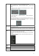
Figure 3-1
Please refer to the following sheet and Figure 3-1 for detailed information.
In the second line,
from the left to the
right,: 1,2,3,4,
5,6,7,8.
ALARM 1 to ALARM 8. The alarm becomes active in low voltage.
In the first line, from
the left to the right:
1-NO C,2-NO C,
3-NO C
There are three groups of normal open activation output (on/off
button)
Earth cable.
485 A/B 485 communication port. They are used to control devices such as
PTZ. Please parallel connect 120TΩ between A/B cables if there are
too many PTZ decoders.
The 16-channel interface is shown as in Figure 3-2.
Figure 3-2
Please refer to the following sheet and Figure 3-2 for detailed information.
In the second line,
from the left to the
right,: 1,2,3,4,
5,6,7,8.and the
first line from the left
to the right : 9,10,
11,12,13,14,
15,16
ALARM 1 to ALARM 16. The alarm becomes active in low voltage.
In the first line, from
the left to the right:
3-NO C,and the
second line from the
left to the right 1-
NO C,2-NO C.
There are three groups of normal open activation output (on/off
button)
Earth cable.
AB cable
connection
AB cable
connection