
Instruction Manual


31
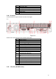
9 HDMI port
10 Video VGA output
11 RS232 port
12 Alarm input/alarm output/RS485 port
13 On/off button
14 Power socket
15 GND port
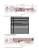
2.2.4 2U series
This series DVR rear panel is shown as below. See Figure
2-9
Figure 2-9
Please refer to the following sheet for detailed information.
1 GND port
2 Power input port
3 Power button
4 Fan
5 DB25 port ( 5
th
to 16
th
-channel audio input port)
6 1
st
to 4
th
-channel audio input
7 Loop video output
8 Video input
9 Video CVBS output
10 Matrix video output
11 Audio output
12 Bidirectional talk input port
13 Bidirectional talk output port
14 Alarm input/Alarm output/RS485 port HDMI
port
15 Video VGA output
16 HDMI port
17 Video CVBS output RS232 port
18 Video matrix output eSATA port
19 USB port
20 Network port
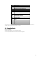
2.2.5 2U series (HD-SDI series)