
User Manual
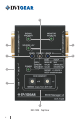

1. DVI INPUT Connect the DVI source device to this connector.
2. BURN Button
Reprograms the attached 8x8 DVIGear Matrix switcher’s EDID data -
this is for legacy support purposes only.
3. 5 VDC INPUT Locking power input connector, +5VDC center pin positive.
4. USB Connector
Advanced EDID Management and rmware upgrades are available via
the USB interface.
5. EDID MEMORY
Select the desired EDID using the two rotary switches – see page 4.
These rotary switches are also used to select HDCP mode – see page 4.
6. LEARN Button
Stores the attached monitor’s EDID data in the selected memory
address between #51 - #79.
7. DVI OUTPUT Connect the display or other downstream sink to this connector.
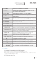
8. Status Indicator LEDs:
SIGNAL PRESENT Indicates if a valid DVI clock signal is present on the DVI IN connector.
MONITOR HOT PLUG
Indicates that a powered display device is connected to the DVI OUT
connector and it is sending a valid hot plug signal.
SOURCE +5V
Indicates if +5V power signal is sent to pin 14 of the input DVI
connector by the DVI source device (e.g. PC, Laptop, etc.)
POWER Indicates that power is being supplied to the device.
EDID / HDCP STATUS Three-color LED that displays the status of the EDID Manager v4
Red Empty memory or invalid EDID is selected
Green Valid EDID data is selected and HDCP pass-through is enabled
Orange Valid EDID data is selected and HDCP pass-through is disabled
Green Flashing Burn / Learn process, or reading connected device’s EDID was successful.
Red Flashing Burn / Learn process, or reading connected device’s EDID failed.
Installation
1.) Connect the DVI source device to the DVI INPUT connector.
2.) Connect the monitor (or sink device) to the DVI OUTPUT connector.
3.) Connect the supplied AC power adapter to the 5 VDC INPUT connector, and then connect the
adapter to a live the AC power outlet.
4.) The unit is now ready for use.
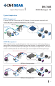
DVI-7425
EDID Manager V4
Quick Start Guide
3