
Service manual
ICD-UX71/UX71F/UX81/UX81F/UX91F
3
1. GENERAL .................................................................. 4
2. DISASSEMBLY
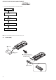
2-1. Cover (USB) ................................................................... 6
2-2. Case Assy ........................................................................ 7
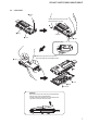
2-3. Audio Board Assy ........................................................... 8
2-4. Main Board Assy ............................................................ 8
3. TEST MODE ............................................................ 9
4. DIAGRAMS
4-1. Block Diagram –Main Section– ..................................... 11
4-2. Block Diagram –Power/Display Section– ...................... 12
4-3. Printed Wiring Board –Audio Section– .......................... 14
4-4. Schematic Diagram –Audio Section (1/3)– .................... 15
4-5. Schematic Diagram –Audio Section (2/3)– .................... 16
4-6. Schematic Diagram –Audio Section (3/3)– .................... 17
4-7. Printed Wiring Board –Main Section– ............................ 18
4-8. Schematic Diagram –Main Section (1/3)– ...................... 19
4-9. Schematic Diagram –Main Section (2/3)– ...................... 20
4-10. Schematic Diagram –Main Section (3/3)– ...................... 21
5. EXPLODED VIEWS
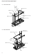
5-1. Case Front Section .......................................................... 31
5-2. Main Board Section ........................................................ 32
5-3. Case Rear Section ........................................................... 33
5-4. Audio Board Section ....................................................... 34
6. ELECTRICAL PARTS LIST .............................. 35
TABLE OF CONTENTS