
User's Manual
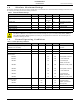
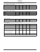
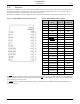
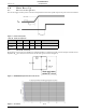
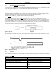
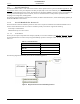
Table Of Contents
- 1.0 Absolute Maximum Ratings
- 2.0 Normal Operating Conditions
- 3.0 Electrical Specifications
- 4.0 Radio
- 5.0 Pinout
- 6.0 Mote Boot Up
- 7.0 Interfaces
- 7.1 Timestamps
- 7.2 Status
- 7.3 Serial Interface
- 7.3.1 Serial Handshake Protocol
- 7.3.2 Mote Command Data Types
- 7.3.3 Mote Commands
- 7.3.3.1 Command 0x80 Serial Payload Sent to Mote Serial
- 7.3.3.2 Command 0x81 Unacknowledged Serial Payload Received from Mote Serial
- 7.3.3.3 Command 0x82 Acknowledged Serial Payload Received from Mote Serial
- 7.3.3.4 Command 0x84 Time/State Packet
- 7.3.3.5 Commands 0x87 and 0x88 Set Parameter Request/Response
- 7.3.3.6 Commands 0x89 and 0x8A Get Parameter Request/Response
- 7.3.3.7 Command 0x8C Mote Information
- 7.3.3.8 Command 0x8D Reset Mote
- 7.3.4 Mote Get/Set Command Parameters
- 7.3.5 HDLC Packet Processing Examples
- 8.0 Packaging Description
- 9.0 Regulatory and Standards Compliance
- 10.0 Ordering Information

Mote Boot Up
8 DUST NETWORKS™ M2135-1/M2030-1 MOTE DATASHEET
CONFIDENTIAL
6.0 Mote Boot Up
6.1 Power-on Sequence
The external supply and other power-on devices must provide the mote with a specific sequence of power and reset as follows:
Figure 3 Power-on Sequence
6.2 Inrush Current
During power on, the mote can be modeled as a lumped impedance of 1 Ohm and 2.5 µF, as shown in Figure 4. With a source
impedance (R
src
) of 2 Ohms, the inrush current on the mote appears as shown in Figure 5.
Figure 4 M2135/M2030 Equivalent Series RC Circuit
Figure 5 Vcc Inrush Current
Table 10 Power-on Sequence
Parameter Min Typ Max Units Comments
T
VccR
500
µs
T
Vcc2RST
10 ms
PRELMINARY