
User's Manual
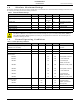
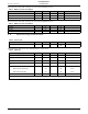
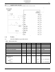
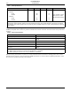
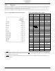
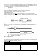
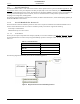
Table Of Contents
- 1.0 Absolute Maximum Ratings
- 2.0 Normal Operating Conditions
- 3.0 Electrical Specifications
- 4.0 Radio
- 5.0 Pinout
- 6.0 Mote Boot Up
- 7.0 Interfaces
- 7.1 Timestamps
- 7.2 Status
- 7.3 Serial Interface
- 7.3.1 Serial Handshake Protocol
- 7.3.2 Mote Command Data Types
- 7.3.3 Mote Commands
- 7.3.3.1 Command 0x80 Serial Payload Sent to Mote Serial
- 7.3.3.2 Command 0x81 Unacknowledged Serial Payload Received from Mote Serial
- 7.3.3.3 Command 0x82 Acknowledged Serial Payload Received from Mote Serial
- 7.3.3.4 Command 0x84 Time/State Packet
- 7.3.3.5 Commands 0x87 and 0x88 Set Parameter Request/Response
- 7.3.3.6 Commands 0x89 and 0x8A Get Parameter Request/Response
- 7.3.3.7 Command 0x8C Mote Information
- 7.3.3.8 Command 0x8D Reset Mote
- 7.3.4 Mote Get/Set Command Parameters
- 7.3.5 HDLC Packet Processing Examples
- 8.0 Packaging Description
- 9.0 Regulatory and Standards Compliance
- 10.0 Ordering Information

Radio
6 DUST NETWORKS™ M2135-1/M2030-1 MOTE DATASHEET
CONFIDENTIAL
4.2 Antenna Specifications
A MMCX-compatible male connector is provided on board for the antenna connection. The antenna must meet specifications
in
Table 8.
When the mote is placed inside an enclosure, the antenna should be mounted such that the radiating portion of the antenna
protrudes from the enclosure, and connected using a MMCX connector on a coaxial cable. For optimum performance, allow
the antenna to be positioned vertically when installed.
Range*
M2135-1:
Indoor
Outdoor
M2030-1:
Indoor
Outdoor
100
400
25
200
m
m
m
m
25 °C, 50% RH, 1 meter
above ground, +2 dBi
omni-directional antenna
* Actual RF range performance is subject to a number of installation-specific variables including, but not restricted to ambient
temperature, relative humidity, presence of active interference sources, line-of-sight obstacles, near-presence of objects
(for example, trees, walls, signage, and so on) that may induce multipath fading. As a result, actual performance varies for
each instance.
Table 8 Antenna Specifications
Parameter Value
Frequency range 2.4–2.4835 GHz
Impedance
50 Ω
Gain +2 dBi maximum
Pattern Omni-directional
Maximum VSWR 3:1
Connector MMCX*
* The M2135-1 can accommodate the following RF mating connectors:
• MMCX straight connector such as Johnson 135-3402-001, or equivalent
• MMCX right angle connector such as Tyco 1408149-1, or equivalent
Table 7 Radio Specifications
Parameter Min Typ Max Units Comments
PRELMINARY