
User's Manual
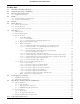
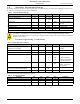
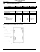
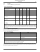
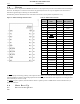
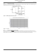
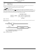
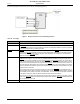
Table Of Contents
- 1.0 Absolute Maximum Ratings
- 2.0 Normal Operating Conditions
- 3.0 Electrical Specifications
- 4.0 Radio
- 5.0 Pinout
- 6.0 Mote Boot Up
- 7.0 Interfaces
- 7.1 Timestamps
- 7.2 Status LED Signal
- 7.3 Serial Interface
- 7.3.1 Serial Handshake
- 7.3.2 Mote Command Data Types
- 7.3.3 Mote Commands
- 7.3.3.1 Command 0x80 Serial Payload Sent to Mote Serial
- 7.3.3.2 Command 0x81 Unacknowledged Serial Payload Received from Mote Serial
- 7.3.3.3 Command 0x82 Acknowledged Serial Payload Received from Mote Serial
- 7.3.3.4 Command 0x84 Time/State Packet
- 7.3.3.5 Commands 0x87 and 0x88 Set Parameter Request/Response
- 7.3.3.6 Commands 0x89 and 0x8A Get Parameter Request/Response
- 7.3.3.7 Command 0x8C Mote Information
- 7.3.3.8 Command 0x8D Reset Mote
- 7.3.4 Mote Get/Set Command Parameters
- 7.3.5 HDLC Packet Processing Examples
- 8.0 Packaging Description
- 9.0 Regulatory and Standards Compliance
- 10.0 Ordering Information

Interfaces
M1310-1 MOTE DATASHEET DUST NETWORKS™ 9
CONFIDENTIAL
7.2 Status LED Signal
The M1310-1 provides an output that can be used to drive a status LED. This signal indicates network connectivity
information which is most useful during mote installation. Alternatively, the mote’s network status may be polled via serial
using the Get Parameter request (see
7.3.3.6) with the mote state parameter (see 7.3.4.3). See Figure 1 for an example
application circuit.
7.3 Serial Interface
The M1310-1 offers a well-defined serial interface that is optimized for low-powered embedded applications. This serial
interface offers a serial port comprised of the data pins (TX, RX) as well as the handshake pins (
MT_RTS, MT_CTS,
SP_CTS) used for bidirectional flow control. Through this port, the M1310-1 provides a means of transmitting and receiving
serial data through the wireless network, as well as a command interface which provides synchronized time stamping, local
configuration and diagnostics.
7.3.1 Serial Handshake
The serial handshake provides for flow control of packets transmitted via the M1310-1 serial interface. Packet delineation and
error control are handled separately. The handshake supports the following:
• Full-duplex communication
• Bidirectional byte-level flow control
7.3.1.1 Serial Port
The five-pin serial port is comprised of the data pins (TX, RX) as well as the handshake pins (MT_RTS, MT_CTS, SP_CTS)
used for bidirectional flow control. This port supports 9600 bps operation in full-duplex mode. The handshake signals are
active low.
Table 9 Status LED Signal
LED Signal Behavior Mote State
High Off, or in sleep mode
Single blink (750 ms low, 3 s high) On, and searching for potential network
Double blink (750 ms low, 750 ms high, 750 ms low, 3 s high) On, and attempting to join the network
Triple blink (750 ms low, 750 ms high, 750 ms low, 750 ms high,
750 ms low, 3 s high)
On, and attempting to establish redundant links
Low On, fully configured into network with redundant parents
Table 10 Serial Parameters
Parameter Value
Bit rate 9600
Stop bit 1
Data bits 8
Parity None
ADVANCED INFORMATION