
User's Manual
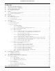
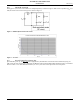
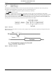
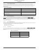
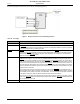
Table Of Contents
- 1.0 Absolute Maximum Ratings
- 2.0 Normal Operating Conditions
- 3.0 Electrical Specifications
- 4.0 Radio
- 5.0 Pinout
- 6.0 Mote Boot Up
- 7.0 Interfaces
- 7.1 Timestamps
- 7.2 Status LED Signal
- 7.3 Serial Interface
- 7.3.1 Serial Handshake
- 7.3.2 Mote Command Data Types
- 7.3.3 Mote Commands
- 7.3.3.1 Command 0x80 Serial Payload Sent to Mote Serial
- 7.3.3.2 Command 0x81 Unacknowledged Serial Payload Received from Mote Serial
- 7.3.3.3 Command 0x82 Acknowledged Serial Payload Received from Mote Serial
- 7.3.3.4 Command 0x84 Time/State Packet
- 7.3.3.5 Commands 0x87 and 0x88 Set Parameter Request/Response
- 7.3.3.6 Commands 0x89 and 0x8A Get Parameter Request/Response
- 7.3.3.7 Command 0x8C Mote Information
- 7.3.3.8 Command 0x8D Reset Mote
- 7.3.4 Mote Get/Set Command Parameters
- 7.3.5 HDLC Packet Processing Examples
- 8.0 Packaging Description
- 9.0 Regulatory and Standards Compliance
- 10.0 Ordering Information

Interfaces
8 DUST NETWORKS™ M1310-1 MOTE DATASHEET
CONFIDENTIAL
7.0 Interfaces
7.1 Timestamps
The M1310-1 has the ability to deliver network-wide synchronized timestamps. The M1310-1 sends a time packet (as
described in
Table 40) through its serial interface when one of the following occurs:
• Mote receives an HDLC Get Parameter request for time/state (see Table 39)
• Mote TIME signal is activated
The TIME pin is optional and has the advantage of being more accurate. The value of the timestamp is taken within
approximately a millisecond of receiving a
TIME signal activation. If the HDLC request is used, because of packet processing,
the value of the timestamp may be captured several milliseconds after receipt of the packet. The real time delivered to the
sensor processor is relative to the real time clock on the Manager which serves as the network real time clock (NRTC). The
time stamp skew across the network is guaranteed to be within ±250 ms of the NRTC.
Figure 5 Real Time
When the time pin is activated for at least min_strobe_length (see Table 12), the mote responds by sending the time packet
within 100 ms delay.
Figure 6 Operation of Time Pin
ADVANCED INFORMATION