
User's Manual
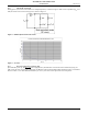
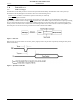
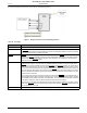
Table Of Contents
- 1.0 Absolute Maximum Ratings
- 2.0 Normal Operating Conditions
- 3.0 Electrical Specifications
- 4.0 Radio
- 5.0 Pinout
- 6.0 Mote Boot Up
- 7.0 Interfaces
- 7.1 Timestamps
- 7.2 Status LED Signal
- 7.3 Serial Interface
- 7.3.1 Serial Handshake
- 7.3.2 Mote Command Data Types
- 7.3.3 Mote Commands
- 7.3.3.1 Command 0x80 Serial Payload Sent to Mote Serial
- 7.3.3.2 Command 0x81 Unacknowledged Serial Payload Received from Mote Serial
- 7.3.3.3 Command 0x82 Acknowledged Serial Payload Received from Mote Serial
- 7.3.3.4 Command 0x84 Time/State Packet
- 7.3.3.5 Commands 0x87 and 0x88 Set Parameter Request/Response
- 7.3.3.6 Commands 0x89 and 0x8A Get Parameter Request/Response
- 7.3.3.7 Command 0x8C Mote Information
- 7.3.3.8 Command 0x8D Reset Mote
- 7.3.4 Mote Get/Set Command Parameters
- 7.3.5 HDLC Packet Processing Examples
- 8.0 Packaging Description
- 9.0 Regulatory and Standards Compliance
- 10.0 Ordering Information

Mote Boot Up
M1310-1 MOTE DATASHEET DUST NETWORKS™ 7
CONFIDENTIAL
6.2 Inrush Current
During power on, the mote can be modeled as a lumped impedance, as shown in Figure 3. With a source impedance (R
src
) of 1
Ohm, the inrush current on the mote appears as shown in Figure 4.
Figure 3 M1310 Equivalent Series RC Circuit
Figure 4 Vcc Inrush Current
6.3 Serial Interface Boot Up
Upon M1310-1 power up, the MT_CTS line is high (inactive). The M1310-1 serial interface boots within boot_delay (see
Table 12) of the mote powering up, at which time the M1310-1 will transmit an HDLC Mote Information packet, as described
below in section 7.3.3.7. Note that full handshake (see 7.3.1.2) is in effect and is required to receive this packet.
ADVANCED INFORMATION