
User's Manual
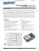
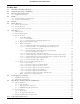
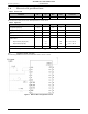
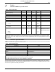
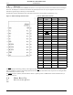
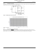
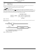
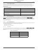
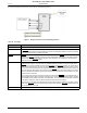
Table Of Contents
- 1.0 Absolute Maximum Ratings
- 2.0 Normal Operating Conditions
- 3.0 Electrical Specifications
- 4.0 Radio
- 5.0 Pinout
- 6.0 Mote Boot Up
- 7.0 Interfaces
- 7.1 Timestamps
- 7.2 Status LED Signal
- 7.3 Serial Interface
- 7.3.1 Serial Handshake
- 7.3.2 Mote Command Data Types
- 7.3.3 Mote Commands
- 7.3.3.1 Command 0x80 Serial Payload Sent to Mote Serial
- 7.3.3.2 Command 0x81 Unacknowledged Serial Payload Received from Mote Serial
- 7.3.3.3 Command 0x82 Acknowledged Serial Payload Received from Mote Serial
- 7.3.3.4 Command 0x84 Time/State Packet
- 7.3.3.5 Commands 0x87 and 0x88 Set Parameter Request/Response
- 7.3.3.6 Commands 0x89 and 0x8A Get Parameter Request/Response
- 7.3.3.7 Command 0x8C Mote Information
- 7.3.3.8 Command 0x8D Reset Mote
- 7.3.4 Mote Get/Set Command Parameters
- 7.3.5 HDLC Packet Processing Examples
- 8.0 Packaging Description
- 9.0 Regulatory and Standards Compliance
- 10.0 Ordering Information

Pinout
6 DUST NETWORKS™ M1310-1 MOTE DATASHEET
CONFIDENTIAL
5.0 Pinout
The M1310-1 has two 11-pin Samtec MTMM-111-04-S-S-175-3 (or equivalent) connectors on the bottom side for handling all
of the I/O. The third pin in each of the connectors is not populated, and serves as a key for alignment. The connectors are
mounted on opposite edges of the long axis of the M1310-1.
The M1310-1 provides a bidirectional flow-controlled serial interface (serial protocol is specified in 7.3.1).
The RST input pin is internally pulled up, and is optional. When driven active low, the mote is hardware reset until the signal
is deasserted. Refer to section
6.1 for timing requirements on the RST pin. Note that the mote may also be reset using the mote
serial command (see section 7.3.3.8).
The TIME input pin is optional, and must either be driven or pulled up with a 5.1 MΩ resistor. Unless noted otherwise, all
signals are active low.
6.0 Mote Boot Up
6.1 Power-on Sequence
TBD
Table 8 M1310-1 Pin Functions
Pin
Number
Name
Mote I/O
Direction
Internal
Pull Up/Down
1 GND - None
2 VCC - None
3 KEY (no pin) - None
4 RX In None
5 TX Out None
6 LED Out None
7 MT_RTS Out None
8 MT_CTS Out None
9 SP_CTS In None
10 TIME In None
11
No Connection
- None
12
No Connection
- None
13
No Connection
- None
14
No Connection
- None
15
No Connection
- None
16
No Connection
- None
17
No Connection
- None
18
No Connection
- None
19
No Connection
- None
20 KEY (no pin) - None
21
No Connection
- None
22 RST In
100 kΩ pull up
Figure 2 M1310-1 Package with Pin Labels
ADVANCED INFORMATION