
User's Manual
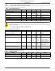
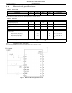
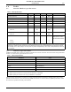
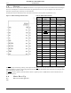
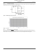
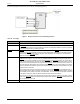
Table Of Contents
- 1.0 Absolute Maximum Ratings
- 2.0 Normal Operating Conditions
- 3.0 Electrical Specifications
- 4.0 Radio
- 5.0 Pinout
- 6.0 Mote Boot Up
- 7.0 Interfaces
- 7.1 Timestamps
- 7.2 Status LED Signal
- 7.3 Serial Interface
- 7.3.1 Serial Handshake
- 7.3.2 Mote Command Data Types
- 7.3.3 Mote Commands
- 7.3.3.1 Command 0x80 Serial Payload Sent to Mote Serial
- 7.3.3.2 Command 0x81 Unacknowledged Serial Payload Received from Mote Serial
- 7.3.3.3 Command 0x82 Acknowledged Serial Payload Received from Mote Serial
- 7.3.3.4 Command 0x84 Time/State Packet
- 7.3.3.5 Commands 0x87 and 0x88 Set Parameter Request/Response
- 7.3.3.6 Commands 0x89 and 0x8A Get Parameter Request/Response
- 7.3.3.7 Command 0x8C Mote Information
- 7.3.3.8 Command 0x8D Reset Mote
- 7.3.4 Mote Get/Set Command Parameters
- 7.3.5 HDLC Packet Processing Examples
- 8.0 Packaging Description
- 9.0 Regulatory and Standards Compliance
- 10.0 Ordering Information

Electrical Specifications
4 DUST NETWORKS™ M1310-1 MOTE DATASHEET
CONFIDENTIAL
3.0 Electrical Specifications
.
Unless otherwise noted, Vcc is 3.0 V and temperature is –40 to +85 °C.
3.1 Application Circuit
The following schematic shows how the M1310-1 mote is used in a circuit.
Figure 1 M1310-1 Mote in Application Circuit
Table 4 Device Load
Parameter Min Typ Max Units Comments
Total capacitance 9.6 12
µF
V
cc
to GND
Table 5 Digital I/O
Digital signal Min Typ Max Units Comments
V
IH
(logical high input) 2.0 3.6 V
V
IL
(logical low input) GND – 0.3 GND GND + 0.8 V
V
OH
(logical high output) 2.4 V
V
OL
(logical low output) 0.4 V
Digital current
*
Output source (single pin) 3.7 mA V
OH
= 2.3 V, 25 °C
Output sink (single pin) 2.0 mA V
OL
= 0.4 V, 25 °C
Input leakage current (TBD) nA
*
This current level guarantees that the output voltage meets V
OL
of 0.4 V and V
OH
of 2.4 V.
ADVANCED INFORMATION