
User's Manual
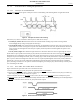
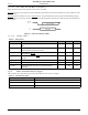
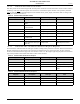
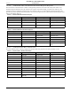
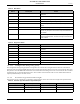
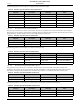
Table Of Contents
- 1.0 Absolute Maximum Ratings
- 2.0 Normal Operating Conditions
- 3.0 Electrical Specifications
- 4.0 Radio
- 5.0 Pinout
- 6.0 Mote Boot Up
- 7.0 Interfaces
- 7.1 Timestamps
- 7.2 Status LED Signal
- 7.3 Serial Interface
- 7.3.1 Serial Handshake
- 7.3.2 Mote Command Data Types
- 7.3.3 Mote Commands
- 7.3.3.1 Command 0x80 Serial Payload Sent to Mote Serial
- 7.3.3.2 Command 0x81 Unacknowledged Serial Payload Received from Mote Serial
- 7.3.3.3 Command 0x82 Acknowledged Serial Payload Received from Mote Serial
- 7.3.3.4 Command 0x84 Time/State Packet
- 7.3.3.5 Commands 0x87 and 0x88 Set Parameter Request/Response
- 7.3.3.6 Commands 0x89 and 0x8A Get Parameter Request/Response
- 7.3.3.7 Command 0x8C Mote Information
- 7.3.3.8 Command 0x8D Reset Mote
- 7.3.4 Mote Get/Set Command Parameters
- 7.3.5 HDLC Packet Processing Examples
- 8.0 Packaging Description
- 9.0 Regulatory and Standards Compliance
- 10.0 Ordering Information

Interfaces
M1310-1 MOTE DATASHEET DUST NETWORKS™ 13
CONFIDENTIAL
7.3.3 Mote Commands
The mote command interface provides a way to send and receive network packets, access local configuration and diagnostics,
and receive time stamps. All packets between the microcontroller and the mote are encapsulated in the HDLC format
(RFC
1662) and have the following structure.
The command type indicates which API message is contained in the message content. The message content for each command
type is described within the following sections.
FCS is calculated based on 16-bit FCS computation method (RFC 1662). The mote checks the FCS and drops packets that
have FCS errors. There is no mechanism for the mote to tell the microcontroller that a packet has been discarded, so the
applications layer must implement reliable delivery, if desired. All numerical fields in a packet are in big endian order (MSB
first), unless otherwise noted. Section
7.3.5 provides an example of HDLC packet construction and HDLC packet decoding.
Table 14 provides a summary of mote commands, which are described in detail in the following sections. For error handling,
all other packet types should be ignored.
Table 14 Mote Command Summary
Command Type (HEX) Direction Description
0x80 Microcontroller to Mote Packet destined for the network
0x81 Mote to Microcontroller Unacknowledged packet received from
the network and destined for
microcontroller
0x82 Mote to Microcontroller Acknowledged packet received from
the network and destined for
microcontroller
0x83 -- Reserved
0x84 Mote to Microcontroller Time and mote state information
0x85 -- Reserved
0x86 -- Reserved
0x87 Microcontroller to Mote “Set Parameter” request
0x88 Mote to Microcontroller “Set Parameter” response
0x89 Microcontroller to Mote “Get Parameter” request
0x8A Mote to Microcontroller “Get Parameter” response
0x8C Mote to Microcontroller Mote information
0x8D Microcontroller to Mote Reset mote
Command
(Byte 1) (Bytes 2—n)
Command Type Message Content
Start Delimiter
(Byte 0)
Data Frame
(Bytes 1—n)
Checksum
(Bytes n + 1, n + 2)
End Delimiter
(Byte n + 3)
0x7E HDLC Packet Payload FCS (2 Bytes) 0x7E
ADVANCED INFORMATION