
User's Manual
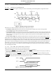
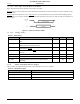
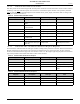
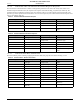
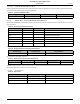
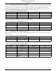
Table Of Contents
- 1.0 Absolute Maximum Ratings
- 2.0 Normal Operating Conditions
- 3.0 Electrical Specifications
- 4.0 Radio
- 5.0 Pinout
- 6.0 Mote Boot Up
- 7.0 Interfaces
- 7.1 Timestamps
- 7.2 Status LED Signal
- 7.3 Serial Interface
- 7.3.1 Serial Handshake
- 7.3.2 Mote Command Data Types
- 7.3.3 Mote Commands
- 7.3.3.1 Command 0x80 Serial Payload Sent to Mote Serial
- 7.3.3.2 Command 0x81 Unacknowledged Serial Payload Received from Mote Serial
- 7.3.3.3 Command 0x82 Acknowledged Serial Payload Received from Mote Serial
- 7.3.3.4 Command 0x84 Time/State Packet
- 7.3.3.5 Commands 0x87 and 0x88 Set Parameter Request/Response
- 7.3.3.6 Commands 0x89 and 0x8A Get Parameter Request/Response
- 7.3.3.7 Command 0x8C Mote Information
- 7.3.3.8 Command 0x8D Reset Mote
- 7.3.4 Mote Get/Set Command Parameters
- 7.3.5 HDLC Packet Processing Examples
- 8.0 Packaging Description
- 9.0 Regulatory and Standards Compliance
- 10.0 Ordering Information

Interfaces
M1310-1 MOTE DATASHEET DUST NETWORKS™ 11
CONFIDENTIAL
7.3.1.2 Serial Interface Timing Requirements
7.3.1.2.1 CTS Byte-level Handshake
The following diagram shows generic CTS byte-level flow control timing. The following details are applicable to both
MT_CTS and SP_CTS.
Figure 8 CTS Byte-level Flow Control Timing
Timeouts T1, T2, and T3 are defined as follows (refer to Table 12 for values):
• T1:interbyte_timeout—Maximum time between the transmit module sending a byte and the receiving module
acknowledging the byte using CTS (requests the next byte).
• T2: interpacket_delay—For communications into the mote, the minimum time after the mote receives the last byte of a
packet before it can start receiving the next packet. For communications out of the mote, the minimum time between the
mote receiving acknowledgement of the last byte reception (or timeout) and the mote driving RTS to request to send
another packet.
• T3: min_strobe_length—The minimum length of time that CTS must be held active to be recognized by the receiver.
In idle mode or upon expiration of the interbyte_delay timeout, the transmit side treats CTS as level triggered (MT_CTS is
disregarded in case of diagnostic serial packets). After transfer of the first byte of a packet, the meaning of CTS signal is
changed to a byte acknowledgement strobe, active on a falling edge. In other words, CTS becomes a request signal for the next
byte of a packet. This acknowledgement strobe will occur for all packets (both diagnostic and network packets). Whenever
timeouts T1 or T2 occur, the packet is discarded and both sides switch to idle mode and start hunting for the next HDLC
packet, assuming CTS active low. If a packet is transferred completely, the interbyte_delay after the last byte naturally takes
care of switching to idle mode.
7.3.1.2.2 Data Flow Out of the Mote Serial Port
Figure 9 illustrates the process the mote uses to transmit serial data:
1. The mote ensures the interpacket_delay time has passed since the last transmission.
2. The mote drives MT_RTS to active, waits for a falling edge on SP_CTS. Timeout is defined as ack_delay (see Table 12),
and is long enough to handle the worst case response.
3. If the mote times out before the SP_CTS becomes active, the mote restores MT_RTS to inactive and drops the packet.
4.
If SP_CTS is active, then the mote transmits the first byte and follows the CTS byte-level handshaking rules for subsequent bytes.
5. MT_RTS is restored to inactive after the ack_delay timeout has expired.
Figure 9 Packet Transmission from Mote
ADVANCED INFORMATION