
User's Manual
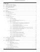
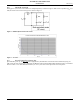
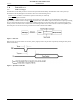
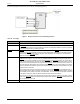
Table Of Contents
- 1.0 Absolute Maximum Ratings
- 2.0 Normal Operating Conditions
- 3.0 Electrical Specifications
- 4.0 Radio
- 5.0 Pinout
- 6.0 Mote Boot Up
- 7.0 Interfaces
- 7.1 Timestamps
- 7.2 Status LED Signal
- 7.3 Serial Interface
- 7.3.1 Serial Handshake
- 7.3.2 Mote Command Data Types
- 7.3.3 Mote Commands
- 7.3.3.1 Command 0x80 Serial Payload Sent to Mote Serial
- 7.3.3.2 Command 0x81 Unacknowledged Serial Payload Received from Mote Serial
- 7.3.3.3 Command 0x82 Acknowledged Serial Payload Received from Mote Serial
- 7.3.3.4 Command 0x84 Time/State Packet
- 7.3.3.5 Commands 0x87 and 0x88 Set Parameter Request/Response
- 7.3.3.6 Commands 0x89 and 0x8A Get Parameter Request/Response
- 7.3.3.7 Command 0x8C Mote Information
- 7.3.3.8 Command 0x8D Reset Mote
- 7.3.4 Mote Get/Set Command Parameters
- 7.3.5 HDLC Packet Processing Examples
- 8.0 Packaging Description
- 9.0 Regulatory and Standards Compliance
- 10.0 Ordering Information

Interfaces
10 DUST NETWORKS™ M1310-1 MOTE DATASHEET
CONFIDENTIAL
The following diagram illustrates the pins used in the handshaking protocol:
Figure 7 Diagram of Pins Used in Handshaking Protocol
Table 11 Pin Usage
Pin Usage
RX, TX Used for serial data flow into and out of the mote.
MT_RTS This signal goes active low when the mote is ready to send a serial packet. The signal stays low until
the
SP_CTS signal from the microcontroller goes active low (indicating readiness to receive a packet)
or the ack_delay timeout (see
Table 12) expires.
SP_CTS SP_CTS should transition from high to active low in response to the MT_RTS signal from the mote.This
indicates that the microcontroller is ready to receive serial packets. Following this, the microcontroller
should strobe
SP_CTS after receiving each byte. After all packets are received, the microcontroller
should de-assert the
SP_CTS signal.
MT_CTS MT_CTS indicates the state of the network connection and availability of data buffers to receive packets
destined for the network. Once the mote has established wireless network connection, it will use the
MT_CTS pin to signify availability to accept serial packets for wireless transmission. At certain critical
times during communication, the mote may bring
MT_CTS high. MT_CTS will remain high if the mote
does not have enough buffer space to accept another packet. It will also remain high if the mote is not
part of the network. OEM designs must check that the
MT_CTS pin is low before initiating each serial
packet for wireless transmission. Note that the mote may receive diagnostic serial packets at any time
regardless of the CTS state.
Upon receipt of the first byte of the HDLC packet, the mote strobes MT_CTS in acknowledgement of
each subsequent byte. After the last byte of the packet is received,
MT_CTS switches back to signaling
the availability of the network connection and data buffers. The microcontroller should wait a minimum
of interpacket_delay (see
Table 12) before initiating another packet transmission.
The mote can accept diagnostics (packets that are not sent through the network) at any time, and the
status of the
MT_CTS pin may be ignored when initiating these packets. (MT_CTS acknowledges each
byte, as specified in
7.3.1.2.1).
TIME The TIME pin is optional and can be used for triggering a timestamp packet. For details, refer to 7.1.
ADVANCED INFORMATION