
User's Manual

Advanced Information
LM2610 User’s Guide Dust Networks™ 9
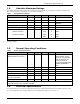
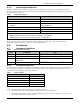
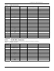
Table 10 J2 MuP JTAG Connector
Pin
Number
Pin Name I/O Direction I/O Type Comment
1 V
DD
In 3.3 V ± 0.3V Supply
2 V
DD
In 3.3 V ± 0.3V Supply
3 Logic 1 Out 3.3V ± 0.3V
4 V
SS
-
5 TDI - 2 JTAG test data in
6 V
SS
-
7
TMS
¯¯¯¯
- 2 JTAG test mode select
8 V
SS
-
9 TCK - 2 JTAG test clock
10 V
SS
-
11 TCK* - 2 JTAG test clock
12 V
SS
-
13 TDO - 2 JTAG test data out
14 V
SS
-
15
RST
¯¯¯¯
In 2 Active low MuP reset
16 V
SS
-
17 V
SS
-
18 V
SS
-
19 V
SS
-
20 V
SS
-
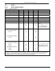
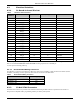
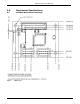
4.2.3 J6 AP SPI+ Connector
The AP SPI+ connector is provided as the mechanism for loading the AP software in production.
Table 11 J6 AP SPI+ Connector
Pin
Number
Pin Name I/O Direction I/O Level Comment
1
SPI_CS
¯¯¯¯¯¯¯
In* 3 SPI chip select
2
FLASH_P_EN
¯¯¯¯¯¯¯¯¯¯¯¯
In* 1 SPI flash program enable
3 SCK In* 3 Serial clock
4 MOSI In* 3 Serial data in
5 MISO Out 3 Serial data out
6
AP_RST
¯¯¯¯¯¯¯
In 1 Access point reset
7 V
DD
In 3.3 V ± 0.3V Supply
8 V
SS
-
9 NC - Reserved
10
RST
¯¯¯¯
In 2 Active low MuP reset