
User's Manual

Advanced Information
8 Dust Networks™ LM2610 User’s Guide
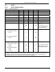
4.2 Electrical Interface
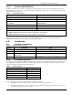
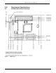
4.2.1 J1 Board-to-board Pin Out
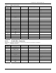
Table 8 J1 Board-to-board Connector
Pin
Number
Pin Name I/O Direction I/O Type Comment
1 V
DD
In 3.3 V ± 0.3V
2 NC - Do Not Connect Reserved
3 V
SS
-
4
RTS_R
¯¯¯¯¯¯
In 2
5 TX Out 4
6
CTS_T
¯¯¯¯¯¯
In 2
7
RTS_T
¯¯¯¯¯¯
Out 2
8 V
SS
-
9
CTS_R
¯¯¯¯¯¯
Out 2
10 RX In 2
11 V
SS
-
12
RTS_A
¯¯¯¯¯¯
Out 2 Reserved
13 TX_A Out 2 Reserved
14
CTS_A
¯¯¯¯¯¯
In** 2 Reserved
15
RTS_B
¯¯¯¯¯¯
In** 2 Reserved
16 V
SS
-
17
CTS_B
¯¯¯¯¯¯
Out 2 Reserved
18 RX_B In 2 Reserved
19 V
SS
-
20
RST
¯¯¯¯
In* 2 Active low MuP reset
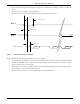
*The RST
¯¯¯
input pin is internally pulled up. When driven low, the LM2610 is hardware reset until the signal is de-asserted.
Refer to section Error! Reference source not found. for timing requirements on the RST
¯¯¯
pin.
** These pins are internally pulled up.
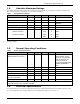
4.2.1.1 Recommended Mating Connectors
The LM2610’s J1 connector is FCIConnect’s Rib-Cage connectors for reliability in high vibration environments (87024-
610TRLF). The mating connector options for this connector are shown in the table below.
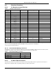
Table 9 Recommended Mating Connectors
Connector Mated Height (mm)
FCI 87409-110LF 5.74
FCI 90098-110LF 7.57
FCI 73547-110LF 9.25
4.2.2 J2 MuP JTAG Connector
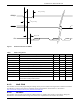
The MuP JTAG connector is provided as the mechanism for loading the MuP software in production. The interface is
designed to be compatible with a programming solution provided by IAR Systems.