
User's Manual

Advanced Information
LM2610 User’s Guide Dust Networks™ 7
t
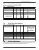
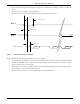
CTS_R to RTS_R
t
RTS_R to CTS_R
RX
0x7EByte 00x7E
t
CTS_R to RX
CTS_R
RTS_R
Figure 2 Packet Transmission to LM2610
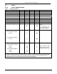
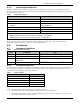
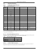
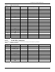
Table 7 UART Timing Values
Variable Description Min Max Units
t
RX_BAUD
Deviation from baud rate -2 +2 %
t
RX_STOP
Number of stop bits (115.2 kbps) 1 bit period
t
TX_BAUD
Deviation from baud rate -1 +1 %
t
TX_STOP
Number of stop bits 1 bit period
t
CTS_R to RTS_R
Assertion of CTS_R
¯¯¯¯¯
to negation of RTS_R
¯¯¯¯¯
0 10 ms
t
RTS_R to CTS_R
Assertion of RTS_R
¯¯¯¯¯
to assertion of CTS_R
¯¯¯¯¯
22 ms
t
CTS_R to RX
Assertion of CTS_R
¯¯¯¯¯
to start of byte
0 10 ms
t
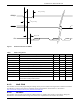
CTS_T to RTS_T
Assertion of CTS_T
¯¯¯¯¯
to negation of RTS_T
¯¯¯¯¯
0 10 ms
t
RTS_T to CTS_T
Assertion of RTS_T
¯¯¯¯¯
to assertion of CTS_T
¯¯¯¯¯
22 ms
t
CTS_T to TX
Assertion of CTS_T
¯¯¯¯¯
to start of byte
0 10 ms
t
interpacket_delay
The sender of an HDLC packet must wait at least this amount
of time before sending another packet
20 ms
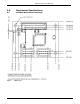
4.1.2 MuP JTAG
This interface can be used for programming the manager micro-processor (MuP) code image before an LM2610 is installed.
The LM2610 J3 connector and pinout is compatible with the AT91SAM-ICE JTAG emulator, as described in
http://www.atmel.com/dyn/resources/prod_documents/doc6206.pdf
.
4.1.3 AP SPI+
This interface can be used for programming the LM2610 before it is installed. This interface is described in “Design for
Manufacture” in the 040-0051DN2510 Integration Guide, and is implemented on the LM2610 J4 connector.