
User's Manual

Advanced Information
LM2610 User’s Guide Dust Networks™ 5
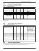
3.1.2 Antenna Specifications
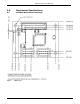
A MMCX-compatible jack receptacle is provided on board for the antenna connection. For antenna location, refer to the
mechanical drawing in section 5.1. The antenna must meet specifications in Table 4. For a list of antennae pre-approved for
RF certification, see section 6.1.2.
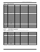
Table 4 Antenna Specifications
Parameter Value
Frequency range 2.4–2.4835 GHz
Impedance
50 Ω
Gain
LM2610-1 +2 dBi maximum
Pattern Omni-directional
Maximum VSWR 3:1
Connector MMCX*
* The LM2610 can accommodate the following RF mating connectors:
• MMCX straight connector such as Johnson 135-3402-001, or equivalent
• MMCX right angle connector such as Tyco 1408149-1, or equivalent
When the LM2610 is placed inside an enclosure, the antenna should be mounted such that the radiating portion of the
antenna protrudes from the enclosure, and connected using a MMCX connector on a coaxial cable. For optimum
performance, allow the antenna to be positioned vertically when installed.
4.0 Interfaces
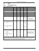
4.1 Hardware Interfaces
Table 5 Hardware Interface Summary
Port Description Pins
Serial UART 6-pin
RTS_T
¯¯¯¯¯¯
, CTS_T
¯¯¯¯¯¯
, TX, RTS_R
¯¯¯¯¯¯
, CTS_R
¯¯¯¯¯¯
, RX, VSS
Reset Active low reset input
RST
¯¯¯¯
MuP JTAG
Programming & development of
LM2610 code
TMS
¯¯¯¯
, TCK TDI, TDO, V
SS
AP SPI+ Programming of the AP
FLASH_P_EN
¯¯¯¯¯¯¯¯¯¯¯¯
, SCK, MOSI, MISO, SPI_CS
¯¯¯¯¯¯¯
, V
DD
, V
SS
4.1.1 3V RS232 Interface
The serial interface is designed for embedded integration with controllers. This serial interface provides programmatic access
for configuration, management, and data access to the LM2610. The port is a 6-pin flow-controlled LVTTL (3.3 V) serial
interface accessible through the board-to-board connector.
Table 6 Serial Parameters
Parameter Value
Bit rate 115200
Parity N
Data bits 8
Stop bit 1
Flow control Hardware handshake
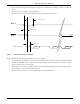
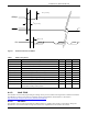
Figure 1 illustrates the process that the LM2610 uses to transmit serial data:
1. The LM2610 ensures the interpacket_delay time has passed since the last transmission.
2. The LM2610 drives RTS_T
¯¯¯¯¯
to active, waits for a falling edge on CTS_T
¯¯¯¯¯
. Timeout is defined as ack_delay, and is
long enough to handle the worst-case response.