H868 Operating Manual
All rights reserved. Property of Dürkopp Adler AG and protected by copyright. Any reuse of these contents, including extracts, is prohibited without the prior written approval of Dürkopp Adler AG.
Table of contents 1 About this manual ...............................................................................3 1.1 1.2 1.3 1.4 1.5 1.6 1.7 Area of applicability ...............................................................................3 Target group ..........................................................................................3 Symbols and characters used ...............................................................4 Other documents .............................................
Table of contents 6.1 6.2 6.3 6.4 6.5 6.6 6.7 6.8 6.9 6.10 6.11 6.11.1 6.11.2 6.12 6.13 6.13.1 6.13.2 6.13.3 6.14 6.14.1 6.14.2 6.15 6.16 Checking the scope of delivery............................................................47 Removing the transport securing devices ...........................................49 Fitting the frame components ..............................................................49 Fitting the pedal ..................................................................................
About this manual 1 About this manual This operating manual for the special sewing machine H868 was compiled with the utmost care. It contains information and notes in order to make long-term and reliable operation possible. Should you notice any discrepancies or if you have improvement requests, then we would be glad to receive your feedback, Section 5.16 Customer service. Please regard the operating manual as part of the product and keep it in a safe place where it can be easily accessed.
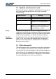
About this manual 1.3 Symbols and characters used Different information is depicted or highlighted in this operating manual by the following characters for easier and quicker understanding: Symbol/character Meaning • Lists are identified by bullet points. 1. Instructions are numbered and have to be performed in the specified order. 2. References to further information in this operating manual or other documents are identified by this symbol.
About this manual 1.5 Liability All information and notes in this operating manual have been compiled in accordance with the latest technology and the applicable standards and regulations. The manufacturer accepts no liability for any damage due to: • • • • • • Breakage and transport Failure to observe the operating manual Improper use Unauthorized modifications to the machine The deployment of untrained personnel Using spare parts not approved 1.
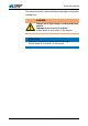
About this manual The manufacturer will not be held liable for damage resulting from improper use. WARNING Danger due to high voltage, crushing and sharp objects. Improper use can result in injuries. Please follow all instructions in the manual. ATTENTION Improper use could result in material damage. Please follow all instructions in the manual. 6 Operating manual H868 Version 00.
Performance description 2 Performance description The Dürkopp Adler special sewing machine H868 is equipped with an extra-large 3XL hook with a 40 mm bobbin diameter. The clearance under the sewing feet when lifted is max. 25 mm. The subclasses have a DC drive with a reversing mechanism, required in order to position the needle above the feet. The special sewing machine positions the needle at the end of the seam and has an electropneumatic foot lifter above the sewing pedal.
Performance description 2.2 Declaration of conformity (CE) The machine complies with the European regulations specified in the declaration of conformity or in the installation declaration. 2.3 Additional equipment A flexible system of additional equipment allows optimal, low-cost equipping of the special sewing machine to suit the respective application.
Performance description Order number Additional equipment H868190361 H868290361 N800 080033 Swiveling end stop, with stop, roller and seam middle guide N800 005650 Seam center guide from front, pneumatically switched 9835 901005 Memo dongle, external memory, for data transmission with DA Classic control 0867 590984 Thread clamp with thread wiper function (FK kit) 9081 300001 Tool set for M-type 0867 590684 Electronic handwheel MG55 400364 Frame set for motor,
Performance description H868190361 Technical data H868290361 Number of stitches on delivery 1600 Stitch quantity reduction for stitch lengths of 6 – 12 mm 1200 Stitch quantity reduction for strokes of 1 – 3 mm 1800 Reduction of the number of stitches with stroke exceeding 4 mm 1500 Reduction of the number of stitches with stroke exceeding 6 mm 1200 Reduction of the number of stitches with stroke exceeding 9 mm 1000 Maximum stroke height (only with reversing mechanism) 25 Maximum sewing foo
Safety instructions 3 Safety instructions This section contains basic instructions for your safety. Read the instructions carefully before setting up, programming, maintaining, or operating the machine. Make sure to follow the information included in the safety instructions. Failure to do this can result in serious injury and damage to the machine. 3.1 Basic safety instructions The machine may only be used as described in this manual.
Safety instructions Requirements to be met by the personnel The machine may only be set up by qualified specialists. Maintenance work and repairs may only be carried out by qualified specialists. Work on electrical equipment may only be carried out by qualified specialists. Only authorized persons may work on the machine. Every person who works on the machine must have read the operating manual first. Operation Inspect the machine while in use for any externally visible damage.
Safety instructions Symbol Type of danger Danger due to electric shock Danger due to sharp objects Danger due to crushing Examples Examples of the layout of the safety instructions in the text: DANGER Type and source of the danger Consequences in the event of noncompliance Measures for avoiding the danger This is what a hazard note looks like for a hazard that will result in serious injury or even death if not complied with.
Safety instructions ATTENTION Type and source of the danger Consequences in the event of noncompliance Measures for avoiding the danger This is what a hazard note looks like for a hazard that could result in material damage if not complied with. ATTENTION Type and source of the danger Consequences in the event of noncompliance Measures for avoiding the danger This is what an hazard note looks like for a hazard that could result in environmental damage if not complied with.
Device description 4 Device description Figure 1: Product overview 12 1 11 2 10 3 9 4 8 5 7 6 (1) - Unwinding bracket with thread reel holder (2) - Handwheel (3) - Bobbin winder for the hook thread (4) - Oil level indicator (5) - Adjusting wheels for the stitch length (6) - Stitch adjustment lever Operating manual H868 Version 00.
Device description 16 Operating manual H868 Version 00.
Operation 5 Operation 5.1 Switching the power supply on and off The lower main switch (2) on the control regulates the power supply. Figure 2: Switching the power supply on and off 1 2 3 4 (1) (2) (3) (4) - Switch for the sewing lamp Main power supply switch Indicator lamp on the controller Indicator lamp on the keypad for quick functions To switch on the power: • Press the main switch (2) down to position I. The indicator lamps (3) and (4) light up.
Operation 5.2 Inserting and replacing the needle WARNING Risk of injury by the needle point and moving parts Switch off the sewing machine before replacing the needle. Do not touch the needle point. Figure 3: Inserting and replacing the needle 1 4 2 (1) (2) (3) (4) - Needle bar Needle screw Hook Groove 3 1. Turn the handwheel back until the needle bar (1) reaches the upper end position. 2. Loosen the needle screw (2). 3. Pull the needle out towards the bottom. 4. Insert the new needle. 5.
Operation WARNING Damage to the hook point or needle possible due to incorrect distance from the hook. The distance between the hook and the needle only needs to be adjusted if the new needle has a different size. After changing the needle size, adjust the hook distance. For more information see Service manual. 5.3 Threading in the needle thread WARNING Risk of injury by the needle point and moving parts Switch off the sewing machine before inserting the thread.
Operation Figure 5: Threading procedure for needle thread – part 1 1 2 4 5 6 9 3 4 5 6 8 7 (1) (2) (3) (4) (5) - First thread guide Second thread guide Pre-tensioner Additional tensioner Main tensioner (6) (7) (8) (9) - Additional screw Thread tensioning spring Spring tip Tightening lever 1. Insert the thread from the rear to the front through the left hole in the 1st thread guide (1). 2.
Operation Figure 6: Threading procedure for needle thread – part 2 10 16 15 11 (10) (11) (12) (13) (14) (15) (16) - Thread lever Thread regulator Needle eye Thread guide on the needle bar Lower thread guide Upper thread guide Hook 14 13 12 9. Guide the thread under the hook (16). 10. Insert the thread from bottom to top through the hole on the thread regulator (11). 11. Insert the thread from the right to the left through the thread lever (10). 12.
Operation 2-needle machines Note on 2-needle machines: 2-needle machines are equipped with a second tensioning screw triangle for the 2nd needle thread. The threading-in procedure corresponds to that for the 1st needle thread. 1 – – 2 + + Figure 7: Needle thread threading procedure for 2-needle machines – + (1) - Tensioning screws in triangular arrangement for the second needle thread (2) - Tensioning screws in triangular arrangement for the first needle thread – + + – + 1234 + – – 1.
Operation Figure 8: Thread guide on the unwinding bracket and machine arm (1) - Thread stand (2) - Guide on the unwinding bracket 2 1 1. Fit the thread reel on the thread reel holder (1). 2. Insert the thread from the rear to the front through a hole in the guide on the unwinding bracket (2). Figure 9: Winding on the hook thread - part 1 1 5 2 4 5 6 4 4 5 6 3 (1) - 1st thread guide (2) - Hook thread guide (3) - Winder (4) - Hook thread winding tension (5) - 2nd thread guide 1.
Operation 3. Guide the thread clockwise around the hook thread winding tensioner (4). 4. Insert the thread in a wavelike manner through the 2 holes of the hook thread guide (2): from bottom to top through the left hole and from top to bottom through the right hole. 5. Guide the thread to the winding bobbin (3). Figure 10: Winding on the hook thread - part 2 1 (1) - Cutter (2) - Winder (3) - Winding lever 2 3 1. Clamp the thread behind the cutter (1) and tear off the loose end behind it. 2.
Operation reel onto the bobbin. When the bobbin is full, the machine automatically stops winding. The bobbin lever moves down. The cutter is automatically moved into its basic vertical position. 3. Pull off the full bobbin. 4. Tear off the thread behind the cutter. 5. Insert a full bobbin in the hook (see Section 5.5 Replacing the hook thread bobbin). 6. Repeat the winding-on procedure with an empty bobbin, as described above. 5.
Operation 4. Guide the hook thread through the 1st hook slot (2). 5. Pull the hook thread under the hook spring (3). 6. Guide the hook thread through the 2nd hook slot (5). 7. Press the hook flap (1) down. 8. Insert the hook thread through the hook flap guide (4). 9. Turn the handwheel until the hook thread comes up. 10. Pull the hook thread and needle thread back together and hold them tight when sewing starts, to avoid jamming the threads. 5.
Operation 5.6.1 Adjusting the needle thread tension The 3 tension-adjusting wheels on the tensioning screw triangle determine the needle thread tension. Figure 13: Adjusting the needle thread tension 1 2 (1) - Pre-tensioner (2) - Additional tensioner (3) - Main tensioner 3 The main tensioner (3) determines the normal tension during sewing. The additional tensioner (2) increases the tension during sewing, e.g. for thickened seams. The additional tension (2) is switched on and off using the keypad.
Operation 5.6.2 Adjusting the hook thread tension WARNING Risk of injury by the needle point and moving parts Switch off the sewing machine before adjusting the hook thread tension. Figure 14: Adjusting the hook thread tension 1 (1) - Adjusting screw The hook thread tension is adjusted using the adjusting screw (1). To increase the tension: • Turn the adjusting screw (1) clockwise. To reduce the tension: • Turn the adjustment screw (1) counterclockwise. 28 Operating manual H868 Version 00.
Operation 5.7 Setting the thread regulator WARNING Risk of injury by the needle point and moving parts Switch off the sewing machine before setting the thread regulator. The thread regulator determines the tension applied to guide the needle thread around the hook. Correct setting: The loop of the needle thread slides at low tension over the thickest point of the hook. Figure 15: Setting the thread regulator 1 (1) - Thread regulator (2) - Regulator screw 2 1. Loosen the regulator screw (2). 2.
Operation 5.8 Lifting the sewing feet You use the foot pedal to raise the sewing feet while sewing, e. g. to move the sewn material. Figure 16: Foot pedal 1 (1) - Foot pedal • Press the foot pedal (1) half the way back. The machine stops and raises the sewing feet. The sewing feet remain up as long as the foot pedal is pressed back half the way. If the foot pedal is pressed back completely, the machine sews an end strip and stops sewing. Machines with automatic thread cutter cut the thread off. 5.
Operation To hold the sewing feet in the upper position: • Push the lever down. To cancel the lock: • Push the lever up. You can also use the foot pedal to cancel the upper position: • Press the foot pedal halfway back as when lifting the sewing feet. The lever swivels back up and the lock is removed. CAUTION Risk of crushing when lowering the sewing foot. Do not hold your hands under the sewing foot when the upper position is released via the pedal or lever. 5.
Operation To reduce the sewing foot pressure: • Turn the adjusting wheel (1) counterclockwise. ATTENTION Damage to the material possible if the sewing foot pressure setting is incorrect. If the sewing foot pressure is too high, the material could tear. If the sewing foot pressure is too weak, the material could slip. Adjust the sewing foot pressure in such a way that the material to be sewn slides smoothly over the base without slipping. 5.
Operation The right adjusting wheel (2) determines the elevated sewing foot stroke. It is used for example when sewing thicker parts of the material. Figure 20: Knee lever 1 (1) - Knee lever (2) - Switch 2 The elevated sewing foot stroke is activated using the knee lever (1). There is a switch (2) at the back of the knee lever (1), which determines whether the sewing foot stroke is applied continuously or only as long as the knee lever is pressed. For permanent conversion: 1. Turn the switch (2) up. 2.
Operation ATTENTION Machine damage possible if the adjusting wheels are turned using brute force. The machine is designed in such a way that the sewing foot stroke at the right adjusting wheel cannot be set lower than at the left adjusting wheel. Do not attempt to use brute force to set a smaller sewing foot stroke at the right adjusting wheel. The machine automatically adapts the number of stitches to the sewing foot stroke. If you increase the sewing foot stroke, the number of stitches will be reduced.
Operation To reduce the stitch length: • Turn the adjusting wheel clockwise. To increase the stitch length: • Turn the adjusting wheel counterclockwise. You can select two different stitch lengths. The upper adjusting wheel (1) is for the larger stitch length and the lower adjusting wheel (2) is for the smaller stitch length. The larger stitch length is switched on using the stitch length key on the key pad ( Section 5.13 Keypad for quick functions).
Operation Figure 22: Stitch adjustment lever on the machine arm 1 1 0 (1) - Stitch adjustment lever 2 6 5 4 3 10 9 8 7 12 11 mm 4 3 2 1 mm 12 11 10 9 8 7 6 5 0 • Slowly push the stitch adjustment lever (1) down. The stitch length becomes smaller. In the lower end position, the machine sews backwards with the stitch length selected at the adjusting wheels. 5.13 Setting quick functions at the keypad The keys activate specific functions during sewing.
Operation Key for sewing backwards (1): If the key (1) is selected the machine sews backwards. Key for the position of the needle (2): If the key (2) is selected the needle moves to a specific position. This position is determined individually via the parameter settings. For more information see Service manual. On delivery, the machine setting is such that the needle is moved up if the key (2) is selected.
Operation Figure 24: Transferring a key function to the additional switch 6 1 2 3 4 7 5 8 9 (1) (2) (3) (4) (5) (6) (7) (8) (9) - Key for sewing backwards Key for the position of the needle Key for the start and end strips Key for the stitch length Key for the additional thread tension Screw in basic position: slot horizontal Screw activates the additional switch (9): slot vertical Screws for the assignment of the additional switch (9) Additional switch The key function is transferred by turning
Operation 5.14 Sewing The foot pedal starts and controls the sewing process. WARNING Risk of injury from the needle tip when sewing is started unintentionally. Take care not to accidentally press the foot pedal when your fingers are in the needle tip area.
Operation To interrupt sewing: • Release the foot pedal in pedal position 0: The machine stops, needles and sewing feet are down. To continue sewing: • Press the foot pedal forwards in pedal position +1: The machine continues to sew. To sew over thickened seams: • Switch on the elevated sewing foot stroke with the knee lever ( Section 5.11 Sewing foot stroke). To change the stitch length: • Switch on the 2nd stitch length using the key for the quick function ( Section 5.
Operation WARNING Risk of injury by the needle point and moving parts Switch off the sewing machine before carrying out maintenance work. 5.15.1 Cleaning the machine ATTENTION Malfunctions possible due to machine contamination. Sewing dust and thread remains can impair the operation of the machine. Clean the machine at regular intervals as described in the manual. Sewing dust and thread remains must be removed every 8 operating hours using a compressed-air pistol or a brush.
Operation Cleaning procedure: • Switch off the power supply at the main switch. • Remove any sewing dust and thread remains using a compressed-air pistol or a brush. WARNING Risk of injury due to flying particles. Flying dirt particles can get in the eyes, causing injury. Hold the compressed-air pistol in such a way that no particles fly near persons. Take care that no particles fly into the oil pan. ATTENTION Possible damage to the paintwork from solventbased cleaners.
Operation Figure 27: Oil level indicator MAX MIN q w (1) - Refill opening (2) - Maximum level mark (3) - Minimum level mark e • Check the oil level indicator every day: The oil level must always be between the minimum level marking (3) and the maximum level marking (2). Pour in oil through the refill opening (1) as required: 1. Switch off the sewing machine at the main switch. 2. Pour in oil, up to but not past the maximum level marking (2). 3. Switch on the sewing machine at the main switch.
Operation ATTENTION Risk of environmental damage from oil. Oil is a pollutant and must not enter the sewage system or the soil. Carefully collect waste oil and dispose of the waste oil and oil-contaminated machine parts in the legally prescribed manner. 5.15.
Operation Water condensation accumulates in the pressure controller of the maintenance unit. Figure 29: Water level in the pressure controller 6 4 8 2 10 0 q w (1) - Filter element (2) - Water separator (3) - Drain screw e • Check the water level every day: The condensation water must not rise up to the level of the filter element (1). Drain water as required: 1. Switch off the sewing machine at the main switch. 2. Place the collection tray under the drain screw (3). 3.
Operation 5.16 Customer service Contacts for repair in the event of damage to the machine: Dürkopp Adler AG Potsdamer Str. 190 33719 Bielefeld, Germany Tel. +49 (0) 180 5 383 756 Fax +49 (0) 521 925 2594 E-mail: service@duerkopp-adler.com Internet: www.duerkopp-adler.com 46 Operating manual H868 Version 00.
Set-up 6 Set-up WARNING Risk of injury. The machine may only be set up by trained specialists. Wear safety gloves and safety shoes when unpacking and setting up. 6.1 Checking the scope of delivery The delivery scope depends on the order. • Prior to set-up, check that all parts required are present. Operating manual H868 Version 00.
Set-up Figure 30: Delivery scope 1 11 2 3 10 4 5 9 6 4 8 2 10 0 8 7 6 (1) - Thread stand (2) - Machine upper section (3) - Oil pan 48 (4) (5) (6) (7) - Controller Pneumatics Knee lever Pedal (8) - Frame (9) - Drawer (10) - Table plate (11) - Control panel Operating manual H868 Version 00.
Set-up Standard equipment: Machine upper section (2), Oil pan (3), thread stands with unwinding arm (1), controller (4), controller operating panel (11), knee lever (6) Optional additional equipment: Table plate (10), drawer (9), frame (8), pedal (7), pneumatic unit (5), sewing lamp (not illustrated) 6.2 Removing the transport securing devices All transport securing devices must be removed prior to set-up. 1.
Set-up 3. Screw the cross strut (6) onto the foot struts (5). 4. Insert the inner bars (2) in such a way that the longer end of the head section (1) is above the longer end of the foot struts (5). 5. Screw the inner bars (2) tight in such a way that both head sections (1) have the same height. 6.4 Fitting the pedal Figure 32: Fitting the pedal 1 2 (1) - Pedal (2) - Cross strut 1. Fit the pedal (1) on the cross strut (2) and align it in such a way that the middle of the pedal is under the needle. 2.
Set-up Figure 33: Completing the table plate 1 2 7 3 6 4 5 (1) (2) (3) (4) - Thread stand Hole in the table plate Corner projections Oil pan (5) - Drawer (6) - Recesses for the rubber mounts of the hinge (7) - Cable duct 1. Screw the drawer (5) with the left-hand bracket to the underside of the table plate. 2. Screw the oil pan (4) in place under the recess for the machine. 3. Screw the cable duct (7) to the underside of the table plate. 4. Insert the thread stand (1) into the hole. 5.
Set-up 6. Screw the thread real holder and the unwinding bracket onto the thread reel holder (1) in such a way that they are exactly opposite each other. 7. Insert the plug (2) in the hole. 8. Insert the rubber mounts of the hinge in the recesses (6). 9. Insert the rubber corners in the corner protrusions (3) of the recess for the machine. 6.6 Fastening the table plate to the frame Figure 34: Fastening the table plate to the frame 1 (1) - Screw holes and screws 1.
Set-up 6.7 Fitting the controller Figure 35: Fitting the controller 1 3 2 (1) - Screw holder (2) - Controller (3) - Strain relief mechanism 1. Screw the controller (2) onto the 4 screw holders (1) under the table plate. 2. Clamp the power cable of the control (2) into the strain relief mechanism (3). 3. Screw the strain relief (3) under the table plate. Operating manual H868 Version 00.
Set-up 6.8 Fitting the setpoint device Figure 36: Fitting the setpoint device 1 2 3 4 10° (1) - Angle piece (2) - Setpoint device (3) - Pedal rod (4) - Pedal 1. Screw the angle (1) under the table plate. 2. Screw the setpoint device (2) onto the angle piece (1). 3. Pull the pedal rod (3) to the correct length: 10° inclination with pedal (4) released. 4. Attach the pedal rod (3). 54 Operating manual H868 Version 00.
Set-up 6.9 Inserting the machine upper section Figure 37: Inserting the machine upper section 1 2 (1) - Upper hinge parts (2) - Rubber inlays 1. Screw the upper hinge parts (1) onto the machine upper section. 2. Insert the upper hinge parts (1) into the rubber inlays (2). 3. Fold the machine upper section down and insert it in the recess. Operating manual H868 Version 00.
Set-up 6.10 Fitting the oil extraction line Figure 38: Fitting the oil extraction line 1 2 (1) - Oil extraction line hose (2) - Felt mat 1. Fold the machine upper section back. 2. Screw the felt mat (2) into the oil pan with the plastic adapter on the right. 3. Insert the tube of the oil extraction line (1) into the plastic adapter. 56 Operating manual H868 Version 00.
Set-up 6.11 Fitting the knee lever 6.11.1 Fitting the electric knee lever Figure 39: Fitting the electric knee lever 1 (1) - Knee lever (2) - Connecting cable (3) - Plug 2 3 1. Screw the knee lever (1) under the oil pan firmly in place under the table plate. 2. Guide the connecting cable (2) to the back between the oil pan and the control. 3. Insert the plug (3) of the connecting cable in the socket of the control. Operating manual H868 Version 00.
Set-up 6.11.2 Fitting the mechanical knee lever Figure 40: Fitting the mechanical knee lever 1 3 2 (1) - Transmission rod (2) - Hole in the oil pan (3) - Knee lever rod 1. Fold the machine upper section back. 2. Fit the transmission rod (1) in the oil pan. 3. Screw the knee lever (3) rods together. 4. Guide the rod (3) through the hole in the oil pan (2) and connect it to the transmission rod (1). 58 Operating manual H868 Version 00.
Set-up 6.12 Fitting the control panel Figure 41: Fitting the control panel – Part 1 4 1 5 2 3 (1) - Control panel (2) - Control panel bracket (3) - Cable duct (4) - Valve cover (5) - Upper machine cover 1. Unscrew the valve cover (4) and upper machine cover (5). 2. Screw the control panel (1) firmly onto the control panel bracket (2). 3. Install the connecting cable through the cable duct (3). Operating manual H868 Version 00.
Set-up Figure 42: Fitting the control panel – Part 2 6 (6) - Connecting cable 4. Install the connecting cable (6) in the machine arm. 5. Guide the cable through the hole in the table plate. 6. Insert the plug of the connecting cable in the socket of the control. Covers If you have an additional sewing lamp to install as additional equipment: • Leave the cover open until the sewing lamp has been installed and the sewing lamp cable has been laid. 7.
Set-up 6.13 Electrical connection DANGER Danger to life due to electric shock. The machine may only be connected by trained electrical specialists. Disconnect the power plug before carrying out work on the electrical equipment. Make sure the power plug cannot be unintentionally reinserted. The voltage on the type plate of the sewing drive must correspond to the mains voltage. 6.13.1 Fitting the sewing lamp The sewing lamp is an additional component that is not part of the standard delivery package.
Set-up Figure 43: Fitting the sewing lamp 1 (1) - Large hole (2) - 2 small holes 2 1. Either drill through the hole for 1 large hole (1) or through the holes for 2 small holes (2). 2. Screw the sewing lamp holder through the hole on the arm cover. 3. Install the connecting cable in the machine arm and guide the cable through the hole in the table plate ( Section 6.12 Fitting the control panel). 4. Stick the sticker with safety instructions onto the front of the control. 6.13.
Set-up Figure 44: Fitting the sewing lamp transformer 1 (1) - Sewing lamp transformer (2) - Pre-drilled holes 2 1. Screw the sewing lamp transformer (1) in place at the predrilled holes (2) under the table plate. 2. Fasten the connecting cable under the table plate using cable ties. 3. Establish the plug connection to the supply line for the sewing lamp.
Set-up 2. Remove the control. 3. Loosen the adaptor cover screws (3). 4. Connect the supply line: For additionally mounted sewing lights to the X3 connection (1), for integrated LED sewing lights to the 24V/X5 connection (2). 6.13.3 Connecting the direct drive To do this, read the Operating manual DAC basic/classic. Connecting the direct drive consists of the following work: • Insert the plugs of all connecting cables in the sockets on the back of the controller.
Set-up Figure 46: Connecting the pneumatic unit 1 2 4 6 4 8 2 10 0 3 (1) - Machine hose (2) - Maintenance unit (3) - System connection hose (4) - Cross bar 1. Attach the maintenance unit (2) to the upper cross bar (4) of the frame using the bracket, screws and clip. 2. Connect the machine tube (1) coming out of the upper section to the maintenance unit (2) at the top right. 3. Connect the system connection tube (3) to the pneumatic system. Operating manual H868 Version 00.
Set-up 6.14.2 Setting the operating pressure ATTENTION Machine damage possible due to incorrect pressure. An incorrect pressure can cause damage to the machine. The operating pressure for the pneumatic unit is 6 bar. Make sure that the operating pressure is set correctly before putting the machine into operation. Figure 47: Setting the operating pressure (1) - Rotary handle (2) - Pressure indicator 1 6 4 8 2 10 2 0 1. Pull the turning handle (1) up. 2.
Set-up 6.15 Lubrication WARNING Skin injuries due to contact with oil Oil can cause a rash if it comes into contact with the skin. Avoid any skin contact with the oil. If oil gets on your skin, wash the affected skin areas thoroughly. All wicks and felt bits of the upper section are soaked in oil on delivery. This oil is conveyed to the reservoir during use. which is why you should avoid filling too much oil during initial filling.
Set-up ATTENTION Risk of environmental damage from oil. Oil is a pollutant and must not enter the sewage system or the soil.
Set-up 6.16 Sewing test Carry out a sewing test before starting up the machine. Adjust the machine to the requirements of the material to be sewn. To do this, read the corresponding sections in the Operating manual. WARNING Risk of injury by the needle point and moving parts Switch off the sewing machine before replacing the needle, insert the thread, insert the hook thread reel, adjust the hook thread tension and the thread regulator. 1. Insert the needle. 2. Thread in the needle thread. 3.
Set-up 70 Operating manual H868 Version 00.
Decommissioning 7 Decommissioning A number of activities must be performed if the machine is to be shut down for a longer period of time or completely decommissioned. WARNING Risk of injury due to a lack of care. A lack of care or a lack of sufficient technical knowledge when decommissioning the machine can result in serious injuries. Only clean the machine when it is switched off. Avoid contact with oil residues. Allow only trained personnel to disconnect the machine.
Decommissioning 72 Operating manual H868 Version 00.
Disposal 8 Disposal The machine must not be disposed of in the normal household waste. The machine must be disposed of in an appropriate and correct manner according to the national regulations. ATTENTION Risk of environmental damage due to incorrect disposal Incorrect disposal of old oil can result in severe environmental damage. Always observe the legally prescribed regulations for disposal.
Disposal 74 Operating manual H868 Version 00.
Appendix 9 Appendix Dimensions for manufacturing a tabletop, part 1 Operating manual H868 Version 00.
Appendix Dimensions for manufacturing a tabletop, part 2 76 Operating manual H868 Version 00.
Subject to design changes - Printed in Germany - © Dürkopp Adler AG - Original Instructions - 0791 868760 EN - 00.0 - 07/2013 DÜRKOPP ADLER AG Potsdamer Str. 190 33719 Bielefeld Germany Phone +49 (0) 521 925 00 E-Mail: service@duerkopp-adler.com www.duerkopp-adler.