
Operation Manual


Installation
Operating manual 969 - 00.0 - 08/2014 97
7.8 Connecting the pneumatic system
7.8.1 Fitting the maintenance unit
A pneumatic connection package for connecting the pneumatic
maintenance unit is available, Additional equipment, page 9.
It includes:
• System connection hose
(length 5 m, diameter 9 mm)
• Hose glands and couplings
• Connection plugs and sockets
Correct setting
The pressure in the pneumatic system network is 8 – 10 bar.
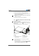
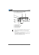
Fig. 53: Installing the maintenance unit pneumatic system
1. Attach the maintenance unit (3) to the upper cross bar (1) of
the frame using the bracket, screws and clip.
2. Plug the hose (4) coming out of the machine upper section
securely into the upper right of the maintenance unit (3).
3. Connect the system supply hose (2) to the pneumatic system.
ATTENTION
Machine damage possible due to incorrect pressure.
Incorrect pressure can result in damage to the machine.
Make sure that the system pressure is set to 8 – 10 bar before
mounting the pneumatic system.
(1) - Cross bar
(2) - System connection hose
(3) - Maintenance unit
(4) - Machine hose
①
②
③
④