
Operation Manual


Installation
Operating manual 969 - 00.0 - 08/2014 89
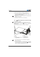
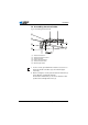
5. Screw on the hinge for the upper left side plate (8).
6. Screw on the holder for the setpoint transducer (4).
7. Turn the frame with the underside upwards and screw the cross
bar (11) to the frame side plates.
8. Important: Set the adjustment support (12) so that the frame
stands level on the floor.
9. From the rear, screw on the oil can holder (6).
7.5.2 Assembling components on underside of table
plate
The table plate is optional.
If you wish to manufacture your own table plate then use the
drawing provided in the appendix, Drawings for creating table
plate, page 105.
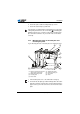
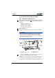
Fig. 49: Assembling components on underside of table plate
1. Turn the table plate over so the underside is facing up.
2. Hammer in the pin (1).
1. Fasten the components as shown in the image. The position
of each component is to scale on the drawing, Component
layout on underside of table plate, page 107.
(1) - Pins
(2) - Buffer
(3) - Fastening clamps for the high
voltage connection
(4) - Drawer
(5) - Fastening clamps
(6) - Lighting transformer
(7) - DAC control unit
①
③
②
④
⑤
⑥
⑦