
Operation Manual


Installation
82 Operating manual 969 - 00.0 - 08/2014
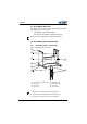
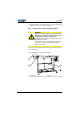
4. Screw the inner bars (2) to the frame bar (3) so that both
headpieces (1) are at the same height.
5. Important: Turn the adjustment screw (5) so the frame is
standing evenly on the floor.
7.4.2 Assembling components on underside of table
plate
The table plate is optional.
If you wish to manufacture your own table plate then use the
drawing provided in the appendix, Drawings for creating table
plate, page 105.
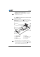
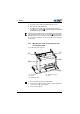
Fig. 44: Assembling components on underside of table plate
1. Turn the table plate over so the underside is facing up.
2. Fasten the components as shown in the image. The position
of each component is to scale on the drawing, Component
layout on underside of table plate, page 107.
(1) - Hinge connecting rod
(2) - Lighting transformer
(3) - Setpoint transducer
(4) - Oil pan
(5) - Drawer
(6) - Frame mounting holes
(7) - Cable duct
(8) - Screw-mounted power cable
mounting clamp
(9) - Nailed mounting clamps
(10) - DAC control unit
①
③
④
⑤
⑥
②
⑦
⑧
⑩
⑨