
Operation Manual

Installation
Operating manual 969 - 00.0 - 08/2014 83
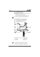
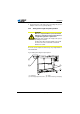
3. Fasten the power cable mounting clamp (8) screws.
4. Nail down the cable clamps (9).
5. Pre-drill the holes in the plate for mounting the frame (6)
according to the drawing, Component layout on underside
of table plate, page 107.
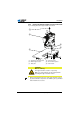
If the machine is equipped with a sewing lamp, first connect the
sewing lamp transformer to the control unit, Connecting the
lighting, page 95. Then screw the control unit to the table plate
(the connection terminal is only accessible when the control unit
is removed).
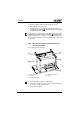
7.4.3 Mounting the frame on the table plate and
mounting the pedal
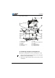
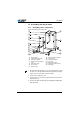
Fig. 45: Mounting frame and pedal
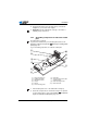
1. Screw the frame (2) at the pre-drilled holes.
2. Screw the foot switch (1) to the vertical cross bar of the frame,
as close as possible to the left bar.
3. Screw on the pedal (5).
(1) - Foot switch
(2) - Frame
(3) - Setpoint transducer
(4) - Pedal connecting rod
(5) - Pedal
①
②
④
⑤
③