
Operating instructions


4.5 Setting the Motor Protection Switch
Motor Type Mains Voltage
3 x 380-400V 3 x 220-230V 3 x 415-440V
FIR 1,6A 2,7A -
Efka VD552/.... 2,5A 4,2A 2,4A
Quick 1,9A 3,3A 1,7A
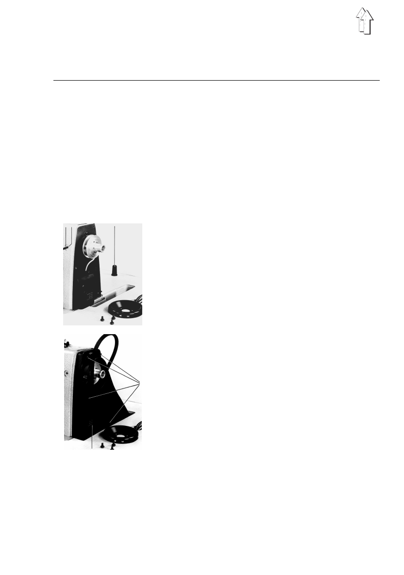
5. Inserting the Machine Head, V-belt Placement, Attaching
the Belt Guard,Handwheel and Pedal
–
Insert the machine head into the table cutout.
–
Tap in the support 2 which is necessary for tilting
over the machine. (Not by classes 273 and 274.)
–
Insert the timing pin 4 found in the accessories
package into one of the slots in the built-in
adjustment disk. Loosen the handwheel screws and
remove the handwheel.
–
By machines with thread trimmer and automatic tying
stitch break the marked opening 6 out of the belt
guard with the aid of a screw driver.
–
As seen in the illustration at the left, one first pushes
the V-belt through the belt guard from the outside
and guides both parts over the belt pulley to the
machine head.
–
Place the V-belt on the belt pulley on the handwheel.
–
Tighten the four screws 5 on the belt guard.
–
Then tilt the machine head to the back and place the
V-belt on the motor pulley.
–
When tilting, the belt guard must enter the table
cutout unimpaired.
–
By slewing the motor, tension the V-belt so that it can
be pressed in at the middle by about 10 mm without
great effort.
–
Screw on the motor belt guard and set its cams so
that the belt remains on the V-belt pulley with the
machine tilted to the back.
43 2
5
6
9